
Plate cutting equipment

A technology for cutting equipment and plates, applied in metal processing equipment, clamping, supporting and other directions, can solve the problems of increasing the worktable area, large limitations, limited plate size, etc., and achieve flexible adjustment, small limitations, and reasonable settings. Effect

Inactive Publication Date: 2017-11-24
贵州恒力源林业科技有限公司
View PDF0 Cites 3 Cited by
  • Summary
  • Abstract
  • Description
  • Claims
  • Application Information

AI Technical Summary

Problems solved by technology

The cutting workbench of many cutting equipment is fixed, so the size of the plate that can be placed on the workbench is relatively limited. If the plate needs to be cut larger, then the area of ​​the workbench must be increased, which will cause serious damage to the cutting of the plate. very limited
[0003] To sum up: the existing plate cutting workbench has the disadvantages that the setting is not very reasonable, the size of the worktable cannot be adjusted, and it is not suitable for the different sizes of the plate to be cut, and the limitations are relatively large.

Method used


Image

  • Plate cutting equipment
  • Plate cutting equipment
  • Plate cutting equipment

Examples


Embodiment Construction

[0019] The present invention will be further described below in conjunction with the accompanying drawings and embodiments, but it is not used as a basis for limiting the present invention.

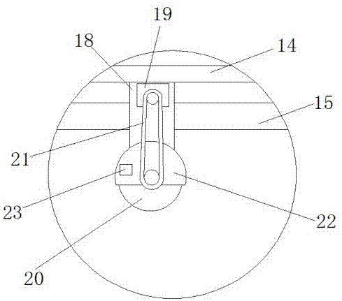
[0020] Example. A kind of plate cutting equipment, constituted as Figure 1-3 As shown, it includes a table top 1, the lower surface of the table top 1 is connected to a set of support columns 2 on the ground, the upper surface of the table top 1 is provided with a chute 3, and a support device 4 is arranged in the chute 3, and the left end of the table top 1 is connected to The first support rod 12, the right end is connected to the second support rod 13, the head ends of the first support rod 12 and the second support rod 13 are connected to the equipment top plate 14, and the rear end of the screw rod 15 passes through the first support rod 12 and is connected to the second support Rod 13, the head end of screw rod 15 is connected with screw motor 16, and screw motor 16 is connected w...


PUM


Abstract

The invention discloses a plate cutting equipment, which comprises a table top, the lower surface of the table top is connected with a group of supporting columns located on the ground, the upper surface of the table top is provided with a chute, and a supporting device is arranged in the chute, and the left end of the table top is connected with a second One support rod, the right end is connected to the second support rod, the head ends of the first support rod and the second support rod are connected to the top plate of the equipment, the tail end of the screw passes through the first support rod and connected to the second support rod, and the head end of the screw is connected to the screw motor , the screw motor is connected to the first support rod through the connecting rod. There is a nut body set on the screw rod under the top plate of the equipment. The head end of the side of the nut body is equipped with a motor. The belt is attached to the mounting shaft of the cutting knife. The invention has the advantages of more reasonable setting, the size of the working table surface can be adjusted, adapting to the different sizes of the required cutting boards, and the limitation is small.

Description

technical field [0001] The invention relates to a machine for cutting boards, in particular to a board cutting device. Background technique [0002] With the development of modern mechanical processing industry, more and more devices and equipment make our life easier and more convenient. In the field of plate cutting, there are also many plate cutting machines. People's requirements for cutting quality and precision are constantly improving, and the requirements for improving production efficiency, reducing production costs, and highly intelligent automatic cutting functions are also increasing. . Some current cutting machines fix the cutting components, drive the plate with a transmission device, and then realize automatic cutting of the plate. In fact, many plates are heavy, and the means of cutting by moving the plate is not very reasonable. The cutting workbench of many cutting equipment is fixed, so the size of the plate that can be placed on the workbench is relativ...

Claims


Application Information

Patent Timeline
Patent Type & Authority Applications(China)
IPC IPC(8): B23D79/00B23Q5/40B23Q3/02
CPCB23D79/00B23Q3/02B23Q5/40
Inventor 林建
Owner 贵州恒力源林业科技有限公司
Learn More