
Endoscope transmission mechanism and endoscope with transmission mechanism

A transmission mechanism and endoscope technology, applied in the field of endoscopes, can solve the problems of difficulty in ensuring welding quality, low production efficiency, and long overall length, avoiding acid mist vapor pollution, easy adjustment and maintenance, and easy assembly. and the effect of disassembly

Pending Publication Date: 2017-11-24
BEIJING HOTWIRE MEDICAL TECH DEV CO LTD
View PDF0 Cites 2 Cited by
  • Summary
  • Abstract
  • Description
  • Claims
  • Application Information

AI Technical Summary

Problems solved by technology

The movement of the two pairs of racks in the lower part of the handle needs to be guided by the rack chute, but the back of the rack after welding is uneven, and it needs to be polished and smoothed for a long time before installation, and it is necessary to test the rack in the rack chute It is time-consuming and labor-intensive, with low production efficiency and high cost.
[0003] After a period of use, with the increase in the number of bending times of the endoscope, the steel wire rope will gradually undergo plastic deformation, and the overall length will become longer, resulting in a reduction in the bending angle of the endoscope. Therefore, the steel wire rope needs to be cut and re-welded for assembly, but In the process of trimming, it is necessary to use a soldering iron to melt, adjust and cut the solder, and then perform welding assembly. This maintenance process is very difficult to operate, and it is difficult to ensure the welding quality when welding the steel wire and the rack again, which creates a problem for installation and maintenance. big problem

Method used


Image

  • Endoscope transmission mechanism and endoscope with transmission mechanism
  • Endoscope transmission mechanism and endoscope with transmission mechanism
  • Endoscope transmission mechanism and endoscope with transmission mechanism

Examples


Embodiment Construction

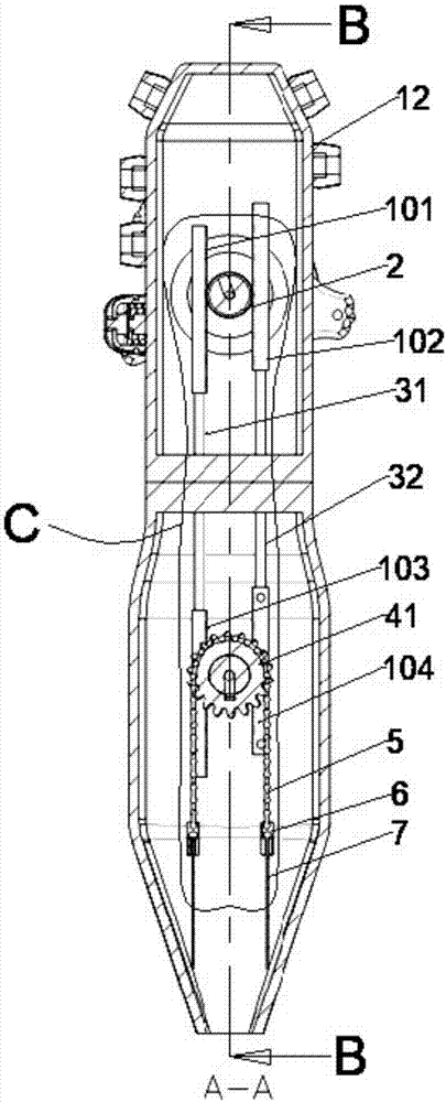
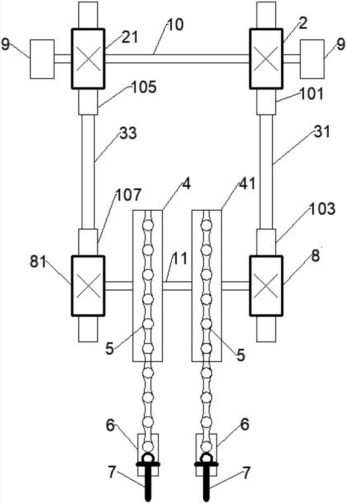
[0025] Such as figure 1 , figure 2 and image 3 As shown, a transmission mechanism of an endoscope includes a driving device 9, a housing 12, a first driving gear 2, a fixed shaft 10 of the driving gear, a first traction rack 101 in the upper section of the housing, a first push rod 31, and a first driving rack 101 in the lower section of the housing. A traction rack 103, the first driven gear 8, the fixed shaft 11 of the driven gear, the first sprocket 4, the chain 5 and the steel wire 7; wherein the driving device 9 is fixedly installed on the housing 12; the first A driving gear 2 is assembled on the fixed shaft 10 of the driving gear, and the fixed shaft 10 of the driving gear is fixedly connected with the driving device 9, and the driving device 9 provides power for the first driving gear 2; The first traction rack 101 in the upper section is meshed with the first driving gear 2, and the first driving gear 2 rotates and drives the first traction rack 101 in the upper s...


PUM


Abstract

The invention discloses an endoscope transmission mechanism and an endoscope with the transmission mechanism. The transmission mechanism comprises a driving device, a shell, an active gear, an upper shell traction rack, a push rod, a lower shell traction rack, driven gears, chain wheels, chains and steel wires; two pairs of racks drive two pairs of driven gears at the lower shell of the endoscope, a chain wheel is attached on the driven gears, chains are arranged on the chain wheel, two ends of the chain are connected with the steel wires respectively, when the racks are driven by the push rod, the racks drive the gears to rotate, the rotation of the gears drives chains to make coaxial synchronous rotation, the connection of the steel wires and chains is fixed using steel wire clamping buckles, welding is not needed, the heavy acid mist vapor pollution and the personal injury to an operator caused by rinsing with concentrated acid when welding the steel wires is avoided, and the adjustment and maintenance at a later stage are also facilitated.

Description

technical field [0001] The invention relates to an endoscope, in particular to a transmission mechanism of the endoscope. Background technique [0002] With the continuous development and progress of electronic science and technology, endoscopes are widely used in the fields of industrial maintenance and medical equipment. The existing endoscope transmission mechanism drives the rotation of two coaxial driving gears in the upper part of the casing respectively through the concentric and coaxial rotation of two hand wheels on the handle, and the two driving gears drive the two pairs of racks in the upper part of the casing to move up and down. The push rod connected under the rack on the upper part of the housing moves up and down accordingly, pushing the two pairs of racks in the lower part of the handle to move, and the two pairs of racks in the lower part, which are internally welded with pulling wires, drive the head end of the insertion part of the mirror body to bend s...

Claims


Application Information

Patent Timeline
IPC IPC(8): A61B1/005G02B23/24
CPCA61B1/0057G02B23/2476
Inventor 王冲
Owner BEIJING HOTWIRE MEDICAL TECH DEV CO LTD
Learn More