Data transmission method and device
A data transmission method and data transmission technology, which are applied in the field of data transmission methods and devices, can solve problems affecting resource usage efficiency, achieve good business requirements, avoid resource waste, and improve usage efficiency
- Summary
- Abstract
- Description
- Claims
- Application Information
AI Technical Summary
Problems solved by technology
Method used
Image


Examples
Embodiment 1
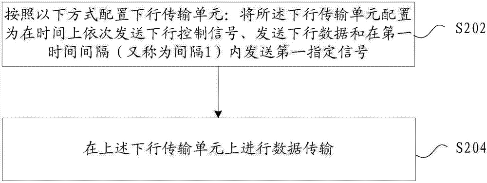
[0058] In this embodiment, a method operating on a 5G mobile communication network architecture is provided. The network architecture includes a base station and a terminal (or called a cellular user), wherein the signal sent by the base station to the terminal is called a downlink signal, and the terminal sends The signal sent by the base station is an uplink signal. In addition, the operation scenario of the data transmission method provided in the present application is not limited to the above network architecture, for example, it is also applicable to the D2D communication architecture (including the D2D sender and the D2D receiver). figure 2 is a flowchart of a data transmission method according to an embodiment of the present invention, such as figure 2 As shown, the process includes the following steps:
[0059] Step S202, configure the downlink transmission unit in the following manner: configure the downlink transmission unit to send downlink control signals, down...
Embodiment 2
[0076] In this embodiment, a data transmission device is also provided, which is used to implement the above embodiments and preferred implementation modes, and what has already been described will not be repeated. As used below, the term "module" may be a combination of software and / or hardware that realizes a predetermined function. Although the devices described in the following embodiments are preferably implemented in software, implementations in hardware, or a combination of software and hardware are also possible and contemplated.
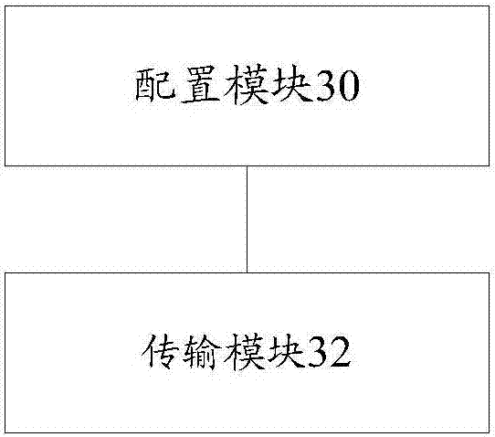
[0077] image 3 is a structural block diagram of a data transmission device according to an embodiment of the present invention, such as image 3 As shown, the device includes:
[0078] The configuration module 30 is configured to configure the downlink transmission unit in the following manner: configure the downlink transmission unit to sequentially send downlink control signals, downlink data and send a first designated signal within a ...
Embodiment 3
[0083] The embodiment of the present application also provides another data transmission method, which can be applied to the data receiving end, such as Figure 4 As shown, the method includes steps S402-S404:
[0084]Step S402, configure the uplink transmission unit in the following manner: configure the above-mentioned uplink transmission unit in sequence in time: send the second specified signal within the second time interval, transmit the uplink data, and transmit the third specified signal within the third time interval and sending an uplink feedback signal, wherein the above-mentioned uplink feedback signal is used for user feedback on downlink data;
[0085] Wherein, the above-mentioned uplink data is used to carry uplink data information. The above-mentioned uplink data information is sent by the cellular user to the base station, or sent by the D2D sender to the D2D receiver.
[0086] Optionally, the second specified signal includes one or more of the following sig...
PUM
 Abstract
Description
Claims
Application Information
 - R&D
- Intellectual Property
- Life Sciences
- Materials
- Tech Scout
- Unparalleled Data Quality
- Higher Quality Content
- 60% Fewer Hallucinations
Browse by: Latest US Patents, China's latest patents, Technical Efficacy Thesaurus, Application Domain, Technology Topic, Popular Technical Reports.
© 2025 PatSnap. All rights reserved.Legal|Privacy policy|Modern Slavery Act Transparency Statement|Sitemap|About US| Contact US: help@patsnap.com