Charging control method and electronic device

A charging control method and technology of electronic equipment, applied in the direction of secondary battery charging/discharging, battery circuit devices, current collectors, etc., can solve the problems of affecting internal resistance, slow charging speed, affecting battery life and battery capacity, and achieve saving production The effect of manufacturing cost and simple structure

Inactive Publication Date: 2017-11-21
HEFEI LCFC INFORMATION TECH
View PDF1 Cites 2 Cited by
  • Summary
  • Abstract
  • Description
  • Claims
  • Application Information

AI Technical Summary

Problems solved by technology

However, the disadvantage of this method is that when the charging enters the constant voltage charging mode, since the charging voltage provided by the charger is constant, the influence of the internal resistance on the charging speed will still occur, and, due to the charging voltage provided by the charger The voltage increase and the temperature change of each electronic component will also affect the internal resistance of the path between the charger and the battery. When the internal resistance becomes larger, the charger still provides a constant charging voltage. Therefore, when charging enters After entering the constant voltage charging mode, the internal resistance will still reduce the charging speed
In addition, too high charging voltage will also affect the life of the battery and the capacity of the battery
[0004] Therefore, aiming at the problem that there is a voltage drop between the power supply voltage received by the existing battery and the charging voltage provided by the charger, which causes the power supply voltage actually received by the battery to be insufficient to meet the charging needs, resulting in a slow charging speed, it is necessary to provide a method that can improve Charging control method and electronic device for charging speed

Method used


Image

  • Charging control method and electronic device
  • Charging control method and electronic device
  • Charging control method and electronic device

Examples


Embodiment Construction

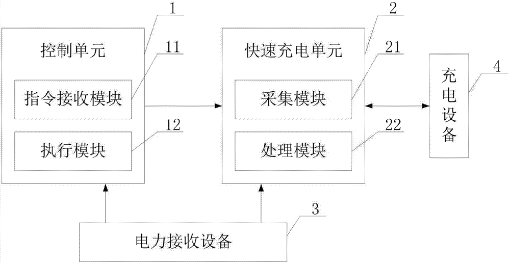
[0029] In the following, the structure and working principle of the embodiment of the present invention will be further described in conjunction with the accompanying drawings.

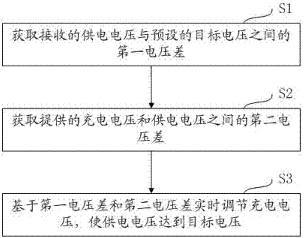
[0030] A charging control method according to an embodiment of the present invention is used to solve the problem that the charging speed is slow due to insufficient voltage actually received by the battery.

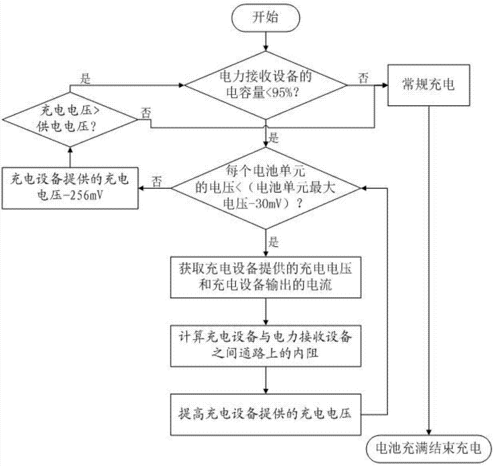
[0031] Because the battery includes two modes of constant current charging mode and constant voltage charging mode during the charging process, and in the constant current charging mode, the charging speed of the battery is very high, only when entering the constant voltage charging mode Only when the charging speed of the battery is affected, it is only necessary to control the charging of the battery when entering the constant voltage charging mode.

[0032] Therefore, the embodiment of the present invention needs to first determine whether the charging mode of the battery has entered the cons...


PUM


Abstract

The invention discloses a charging control method and an electronic device. The charging control method includes the steps: receiving a preset indication and executing rapid charging including: acquiring a first voltage difference between received power supply voltage and preset target voltage; acquiring a second voltage difference between provided charging voltage and power supply voltage; adjusting charging voltage to reach the target voltage in real time based on the first voltage difference and the second voltage difference. The electronic device comprises a control unit and a rapid charging unit, wherein the control unit comprises an indication receiving module and an executing module, and the rapid charging unit comprises an acquisition module and a processing module. According to the charging control method and the electronic device, the voltage difference between the charging voltage provided by a charger and the power supply voltage received by a battery can be acquired in real time, and the problem of slow charging caused by insufficient voltage actually received by the battery is solved according to the voltage difference.

Description

technical field [0001] The invention relates to the technical field of charge control, in particular to a charge control method and electronic equipment. Background technique [0002] With the popularity of electronic product applications, users are paying more and more attention to the charging performance of their batteries. However, when the existing battery is charged to a certain level, due to the influence of internal resistance, the charging mode is changed from a constant current charging mode to a constant voltage charging mode, resulting in the supply voltage received by the battery being different from the charging provided by the charger. The inconsistency between the voltages means that the power supply voltage received by the battery may be lower than the power supply voltage actually required by the battery, thereby reducing the charging speed of the battery and reducing the charging efficiency of the battery. [0003] The power supply voltage received by the...

Claims


Application Information

Patent Timeline
Patent Type & Authority Applications(China)
IPC IPC(8): H02J7/00H01M10/44
CPCH01M10/44H02J7/0077Y02E60/10
Inventor 池咏伦
Owner HEFEI LCFC INFORMATION TECH
Why Eureka
Try Eureka