Frequency conversion refrigerating system of high-power electronic equipment and control method for phase change energy storage apparatus thereof
A technology of electronic equipment and refrigeration system, which is applied to the structural parts of electrical equipment, electrical components, and modification with liquid cooling, which can solve the problems of difficult cooling and energy consumption of high-power electronic equipment, and achieve reasonable structure and simple control method Effect
- Summary
- Abstract
- Description
- Claims
- Application Information
AI Technical Summary
Problems solved by technology
Method used
Image
Examples
Embodiment 1
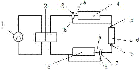
[0010] A frequency conversion refrigeration system for high-power electronic equipment. The frequency conversion refrigeration unit 1 is connected in parallel with the evaporator 2. The outlet pipe ends of the evaporator are respectively connected with first valves 3. The first valves are three-way valves. One channel of the first valves It is communicated with the first phase-changing accumulator 4, and the other passage of the first valve is communicated with the cooling liquid inlet of the external cooling device 6 of the electronic equipment to be cooled; the cooling liquid outlet of the external cooling device of the electronic equipment to be cooled is connected with the first The two valves communicate with 7, the second valve is a three-way valve, one channel of the second valve is communicated with the second phase-distorted accumulator 8, and the other channel of the second valve is communicated with the inlet pipeline of the evaporator; The cooling liquid inlet and t...
Embodiment 2
[0013] A frequency conversion refrigeration system for high-power electronic equipment. The frequency conversion refrigeration unit 1 is connected in parallel with the evaporator 2. The outlet pipe ends of the evaporator are respectively connected with first valves 3. The first valves are three-way valves. One channel of the first valves It is communicated with the first phase-changing accumulator 4, and the other passage of the first valve is communicated with the cooling liquid inlet of the external cooling device 6 of the electronic equipment to be cooled; the cooling liquid outlet of the external cooling device of the electronic equipment to be cooled is connected with the first The two valves communicate with 7, the second valve is a three-way valve, one channel of the second valve is communicated with the second phase-distorted accumulator 8, and the other channel of the second valve is communicated with the inlet pipeline of the evaporator; The cooling liquid inlet and t...
Embodiment 3
[0016] A frequency conversion refrigeration system for high-power electronic equipment. The frequency conversion refrigeration unit 1 is connected in parallel with the evaporator 2. The outlet pipe ends of the evaporator are respectively connected with first valves 3. The first valves are three-way valves. One channel of the first valves It is communicated with the first phase-changing accumulator 4, and the other passage of the first valve is communicated with the cooling liquid inlet of the external cooling device 6 of the electronic equipment to be cooled; the cooling liquid outlet of the external cooling device of the electronic equipment to be cooled is connected with the first The two valves communicate with 7, the second valve is a three-way valve, one channel of the second valve is communicated with the second phase-distorted accumulator 8, and the other channel of the second valve is communicated with the inlet pipeline of the evaporator; The cooling liquid inlet and t...
PUM
| Property | Measurement | Unit |
|---|---|---|
| Phase transition temperature | aaaaa | aaaaa |
| Phase transition temperature | aaaaa | aaaaa |
| Phase transition temperature | aaaaa | aaaaa |
Abstract
Description
Claims
Application Information
 - R&D
- Intellectual Property
- Life Sciences
- Materials
- Tech Scout
- Unparalleled Data Quality
- Higher Quality Content
- 60% Fewer Hallucinations
Browse by: Latest US Patents, China's latest patents, Technical Efficacy Thesaurus, Application Domain, Technology Topic, Popular Technical Reports.
© 2025 PatSnap. All rights reserved.Legal|Privacy policy|Modern Slavery Act Transparency Statement|Sitemap|About US| Contact US: help@patsnap.com

