
Novel rotational rectifying component

A technology of rotating rectification and components, applied in the direction of electric components, electrical components, electromechanical devices, etc., can solve problems such as bolt breakage, and achieve the effect of avoiding breakage and prolonging service life

Active Publication Date: 2017-11-17
JIANGSU HENGTONG GENERATOR MFG
View PDF3 Cites 0 Cited by
  • Summary
  • Abstract
  • Description
  • Claims
  • Application Information

AI Technical Summary

Problems solved by technology

Since the brushless DC motor operates in a self-controlled manner, it does not add a starting winding to the rotor like a synchronous motor with heavy load under variable frequency speed regulation, nor does it cause oscillation and out of step when the load changes suddenly. The motor relies on changing the alternating frequency and waveform of the current wave input to the stator coil of the brushless motor, and forms a magnetic field that rotates around the geometric axis of the motor around the winding coil. This magnetic field drives the permanent magnet steel on the rotor to rotate, and the motor Turning up, the performance of the motor is related to factors such as the number of magnets, the magnetic flux strength of the magnets, and the input voltage of the motor, and has a lot to do with the control performance of the brushless motor, because the input is DC, and the current requires electronic speed regulation. Convert it into three-phase alternating current, and also need to receive control signals from the remote control receiver to control the speed of the motor to meet the needs of the model. The rotating rectifier component in the brushless motor is an important part in daily production and life , it plays a vital role, but during use, due to the large lateral shear force on the bolts during the high-speed rotation, which will cause the bolts to break, which brings great harm to the use constant

Method used


Image

  • Novel rotational rectifying component
  • Novel rotational rectifying component

Examples


Embodiment Construction

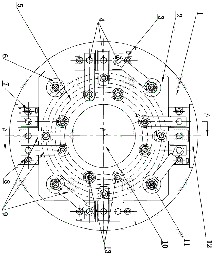
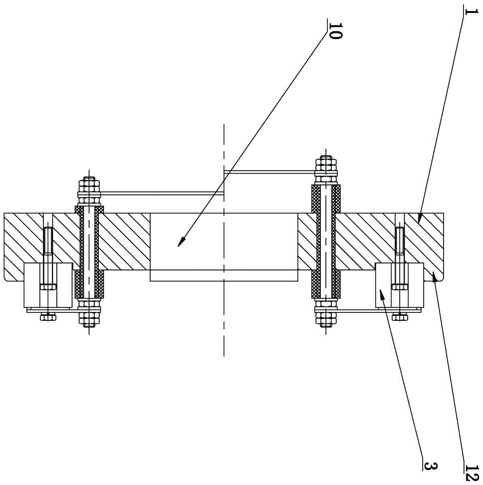
[0015] The purpose of the present invention is achieved in this way: a new type of rotary rectification assembly, including a rectification seat body 1, the rectification seat body 1 is arranged in a circular shape, a square fixing seat 2 is arranged on the rectifying seat body 1, and four square fixing seats 2 The corners are respectively provided with bolt fixing bases 6, bolt fixing holes are arranged between two adjacent bolt fixing bases 6, a large hole 10 is arranged from the center of the square fixing seat 2 to the center of the rectifying seat body 1, and the rectifying seat body 1 Steps 12 are respectively provided at the front, rear, left, and right positions on the top; rectifier disc 5 is provided on the square fixed seat 2, and through-holes 13 are arranged on the position of rectifier disc 5 corresponding to the bolt fixing holes. The rectifier seat body 1 is provided with a fixed block 3, and the fixed block 3 is provided with three sets of connection holes 4, a...


PUM


Abstract

The invention relates to a novel rotational rectifying component in the field of brushless motors. A big hole is formed from the center of a square fixed seat and the center of a rectifying seat body, and steps are arranged at the front, rear, left and right positions of the rectifying seat body; a rectifying disc is arranged on the square fixed seat, through holes are formed in the positions, corresponding to bolt fixed holes, of the rectifying disc in a matched manner respectively, the rectifying seat body between the steps and the square fixed seat is provided with fixed blocks, three groups of connecting holes are formed in the fixed blocks, any two groups of connecting holes in the fixed blocks are fixedly connected with the through holes, close to the fixed blocks, in the rectifying disc through connecting plates, and the other group of connecting holes in any three groups of fixed blocks are connected with a bolt fixed substrate close to the connecting block through connecting plates. The novel rotational rectifying component can be widely applied to the field of brushless motors, the centrifugal force caused during bolt rotation is reduced by adding the fixed blocks, and bolts are avoided from being broken, so that the service life of the rotational rectifying component is prolonged.

Description

technical field [0001] The invention relates to a novel rotating rectifying assembly in the field of brushless motors. Background technique [0002] The brushless DC motor consists of a motor body and a driver, and is a typical mechatronic product. Since the brushless DC motor operates in a self-controlled manner, it does not add a starting winding to the rotor like a synchronous motor with heavy load under variable frequency speed regulation, nor does it cause oscillation and out of step when the load changes suddenly. The motor relies on changing the alternating frequency and waveform of the current wave input to the stator coil of the brushless motor, and forms a magnetic field that rotates around the geometric axis of the motor around the winding coil. This magnetic field drives the permanent magnet steel on the rotor to rotate, and the motor When it turns, the performance of the motor is related to factors such as the number of magnets, the magnetic flux strength of th...

Claims


Application Information

Patent Timeline
IPC IPC(8): H02K11/042
CPCH02K11/042Y02E10/50
Inventor 李树茂
Owner JIANGSU HENGTONG GENERATOR MFG
Learn More