
Power source bus-bar circuit applied to CubeSat

A power bus, cube star technology, applied in battery circuit devices, circuit devices, load supply circuits, etc., can solve problems such as large energy loss, large relay size, and inapplicability to cube star power systems, and achieve cost reduction and functional integration. High degree, simple design and ingenious effect

Active Publication Date: 2017-11-17
NANJING UNIV OF SCI & TECH
View PDF2 Cites 4 Cited by
  • Summary
  • Abstract
  • Description
  • Claims
  • Application Information

AI Technical Summary

Problems solved by technology

[0004] Traditional small satellite busbars mostly use relays as control switches. However, this method is not suitable for CubeSat power system design due to the large size of the relay and high energy loss.

Method used


Image

  • Power source bus-bar circuit applied to CubeSat

Examples


Embodiment Construction

[0028] The present invention will be described in further detail below in conjunction with the accompanying drawings.

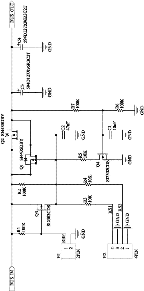
[0029] combine figure 1 , a power bus circuit applied to a cube star, including the first Molex connector H1 (53261-0271), the second Molex connector H2 (53261-0471), the first P-MOS tube Q1 (SI4435DBY), the second P-MOS tube Q2 (SI4435DBY), third P-MOS tube Q3 (SI2303CDS), fourth N-MOS tube Q4 (SI2302CDS), first resistor R1 (100K), second resistor R2 (100K), third resistor R3 (10K), fourth resistor R4 (10K), fifth resistor R5 (10K), sixth resistor R6 (100K), seventh resistor R7 (100K), first ceramic capacitor C1 (10nF), second ceramic capacitor C2 (47µF), third tantalum capacitor C3 (120µF) and fourth tantalum capacitor C4 (120µF).

[0030] The first Molex connector H1 is externally connected to the CubeSat RBF port, and the second Molex connector H1 is externally connected to the CubeSat separation switch. Before the cube star is loaded into the separati...


PUM


Abstract

The present invention discloses a power source bus-bar circuit applied to the CubeSat. A first P- MOS transistor Q1 and a second P- MOS transistor Q2 are connected in parallel; the S pole of the first P- MOS transistor Q1 and the S pole of the second P- MOS transistor Q2 are connected together, and then are connected with one end of a second resistor R2, the S pole of a third P- MOS transistor Q3 and one end of a first resistor R1; the G pole of the first P- MOS transistor Q1 and the G pole of the second P- MOS transistor Q2 are connected together and then are connected with the other end of the second resistor R2, one end of a third resistor R3, one end of a fourth resistor R4, one end of a fifth resistor R5, the D pole of the third P- MOS transistor Q3 and one end of a second ceramic capacitor C2; and the D pole of the first P- MOS transistor Q1 and the D pole of the second P- MOS transistor Q2 are connected together and then are connected with one end of a seventh resistor R7, the positive pole end of a third tantalum capacitor C3 and the positive pole end of a fourth tantalum capacitor C4. The power source bus-bar circuit of the invention has the advantages of small size, high functional integration and small energy loss. With the power source bus-bar circuit adopted, the requirements of de-energization of the CubeSat after a ground test is performed and the independent energization of the CubeSat after the CubeSat enters an orbit can be satisfied.

Description

technical field [0001] The invention belongs to the field of cube star power subsystems, in particular to a power bus circuit applied to a cube star. Background technique [0002] In recent years, with the rapid development of communication, optoelectronic components, materials, sensors, and other technologies, cube satellites with low cost and high functional density have gradually emerged, which greatly reduces the development cost and development cycle of satellites. Remote measurement and testing become possible. [0003] As an important subsystem of the CubeSat, the power system’s task is to ensure safe and reliable power supply to the entire star in orbit. However, due to the limited size and energy, the power system should fully consider the high-efficiency and small-volume design. After the CubeSat is commissioned on the ground and installed in the separation device in the factory, the whole star is required to be in a power-off state; after the cubesat enters orbit...

Claims


Application Information

Patent Timeline
IPC IPC(8): H02J7/00
CPCH02J7/0063H02J2207/10
Inventor 马海宁黄雨晨张翔
Owner NANJING UNIV OF SCI & TECH
Learn More