
An electronic ink display screen and manufacturing method thereof

A technology of electronic ink and manufacturing method, which is applied in the fields of instruments, nonlinear optics, optics, etc., can solve the problems of difficult electronic paper membrane packaging technology, high use cost, unstable process, etc., and achieve rich driving schemes and display effects , Waterproof and sealing performance improvement, the effect of excellent color resolution

Active Publication Date: 2019-03-08
WUXI VISION PEAK TECH
View PDF9 Cites 1 Cited by
  • Summary
  • Abstract
  • Description
  • Claims
  • Application Information

AI Technical Summary

Problems solved by technology

[0005] 1. The preparation process of microcapsule electronic paper membrane is complex:
[0006] a) Microcup electronic paper membrane coating requires high equipment precision, high cost of use, many coating defects, uneven distribution of microcapsules, and uneven coating thickness
[0007] b) The packaging technology of the electronic paper diaphragm (20) is difficult, the process is unstable, the production efficiency is low, and there are problems such as liquid leakage, low contrast, and narrow operating temperature range.
[0008] c) The cutting loss rate of the electronic paper diaphragm (20) is often as high as 40%, resulting in the utilization rate of electronic ink being less than 40%.
[0009] 2. The manufacturing process of electronic ink display is complicated, the degree of production automation is low, the production efficiency is low, the yield rate is low, the material loss is large, and the production cost is high.
So far, the ODF process has not been used in the manufacture of e-ink displays

Method used


Image

  • An electronic ink display screen and manufacturing method thereof
  • An electronic ink display screen and manufacturing method thereof
  • An electronic ink display screen and manufacturing method thereof

Examples


Embodiment Construction

[0054] The present invention will be further described below in conjunction with specific drawings and embodiments.

[0055] The present invention is not limited to the following embodiments, and the figures referred to in the following description are provided for understanding the content of the present invention, that is, the present invention is not limited to the structure of the electronic ink display screen exemplified in each figure.

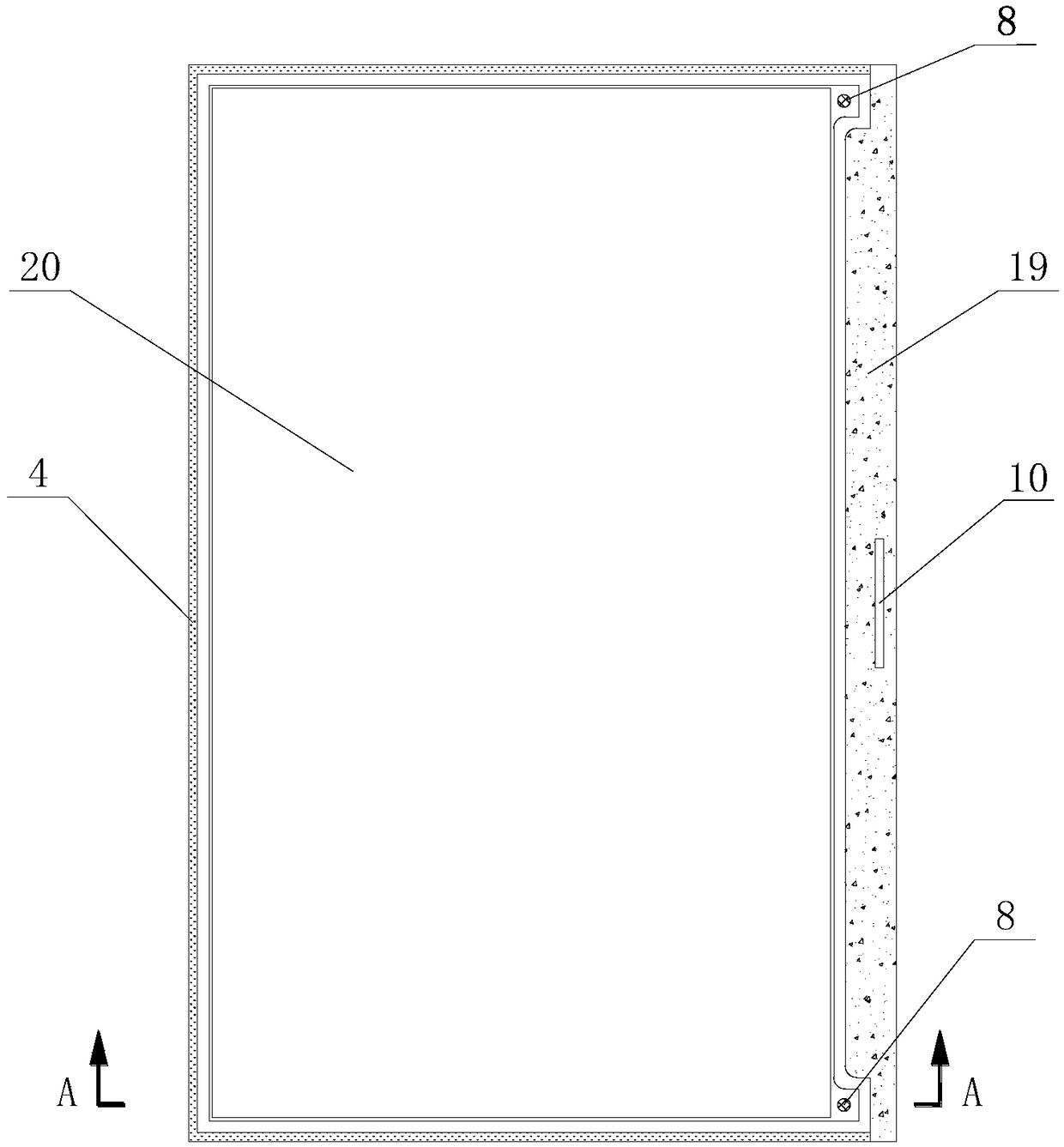
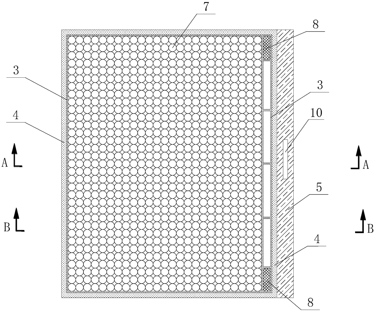
[0056] as attached Figure 3~5 As shown, Embodiment 1 takes a two-particle electronic ink display screen as an example. An electronic ink display screen includes a pixel electrode 5, an electronic ink microcapsule array 7 and an upper transparent electrode, and the electronic ink microcapsule array 7 is arranged on the pixel Between the electrode 5 and the upper transparent electrode, it is characterized in that the pixel electrode 5 includes a segment code and a dot matrix, and the material of the pixel electrode is glass or plastic, an...


PUM

PropertyMeasurementUnit
diameteraaaaaaaaaa
widthaaaaaaaaaa

Abstract

The invention relates to an electronic ink display screen, which is characterized in that a pad frame is coated on a pixel electrode through an ODF process, and the pad frame includes a first pad frame and a second pad frame, and the second pad frame is located at the first pad frame. One side of the liner frame, the first liner frame is provided with an electronic ink microcapsule array, the second liner frame is provided with conductive silver paste, the liner frame is covered with an upper transparent electrode, and the conductive silver paste is respectively connected to the pixel The electrode and the upper transparent electrode are in electrical contact, and the gasket frame and the upper transparent electrode are sealed and fixed by waterproof glue; the electronic ink display of the present invention uses the ODF process to save the complicated production process of the traditional electronic paper film, and directly put the electronic paper film The combined processing of chip production and electronic paper display greatly simplifies the back-end manufacturing process of electronic paper display, shortens the process flow, and improves production efficiency and yield.

Description

technical field [0001] The invention relates to a display screen and a manufacturing method thereof, in particular to an electronic ink display screen and a manufacturing method thereof, belonging to the technical field of electronic display. Background technique [0002] Electrophoretic display technology was first proposed in the 1970s. In the past decade, electrophoretic display technology has been greatly developed, and its performance and manufacturing methods have been greatly improved. Patent US3892568 discloses the preparation process of an electrophoretic display material comprising at least one electrophoretic particle. Patent JP1086116 discloses an electrophoretic display system containing at least one electrophoretic particle and the electrophoretic fluid is encapsulated by microcapsules. In patents US5930026, US5961804, US6017584 and US6120588, microcapsule-coated electrophoretic display units are disclosed, wherein the electrophoretic display liquid contains t...

Claims


Application Information

Patent Timeline
Patent Type & Authority Patents(China)
IPC IPC(8): G02F1/167G02F1/1679G02F1/16757G02F1/1676G02F1/16766
CPCG02F1/167G02F1/1339G02F1/133305G02F1/16757G02F1/1679G02F1/1676G02F1/13415G02F1/1685G02F1/16766G02F1/13439G02F2201/123
Inventor 包进张磊陈山
Owner WUXI VISION PEAK TECH
Learn More