
Manufacturing method and device of electronic paper display device

A technology of a display device and a manufacturing method, applied in the field of display screens, can solve the problems of affecting the brightness, contrast and thickness of an electronic paper display device, failing to display a film layer of electronic paper, increasing the thickness of the display film layer, etc., so as to simplify the back-end manufacturing process , Enriching the drive scheme, saving space and manpower

Active Publication Date: 2022-05-24
广东志慧芯屏科技有限公司
View PDF11 Cites 1 Cited by
  • Summary
  • Abstract
  • Description
  • Claims
  • Application Information

AI Technical Summary

Problems solved by technology

[0006] However, there are problems in both methods. First, the electronic paper display film layer produced by these two methods needs to be produced through complicated coating or coating processes in order to make microcapsules or microcups in the film, and requires Adhesives or film are used to bond microcapsules or microcups together to make a film, and a layer of adhesive or film film is added on the microcapsules or microcups, which will affect the reflection of light through the pigment particles. The transmittance also increases the thickness of the display film layer, thus affecting the brightness, contrast and thickness of the electronic paper display device.
Secondly, the electrophoretic display liquid in the microcapsules or microcups in the electronic paper display film layer of the electronic paper display device is the same, and the microcapsules or microcups coated with different electrophoretic display liquids cannot be made in a regular manner. The electronic paper display film layer, so these two methods can only make monochrome electronic paper display devices

Method used


Image

  • Manufacturing method and device of electronic paper display device
  • Manufacturing method and device of electronic paper display device
  • Manufacturing method and device of electronic paper display device

Examples


Embodiment Construction

[0059] Embodiments of the present invention will be described in more detail below with reference to the accompanying drawings. Although embodiments of the present invention are shown in the drawings, it should be understood that the present invention may be embodied in various forms and should not be limited by the embodiments set forth herein. Rather, these embodiments are provided so that this disclosure will be thorough and complete, and will fully convey the scope of the present invention to those skilled in the art.

[0060] The present invention is described in detail with reference to the schematic diagrams. When describing the embodiments of the present invention in detail, for the convenience of explanation, the sectional views showing the device structure will not be partially enlarged according to the general scale, and the schematic diagrams are only examples, which should not limit the present invention. scope of protection. In addition, the three-dimensional sp...


PUM


Abstract

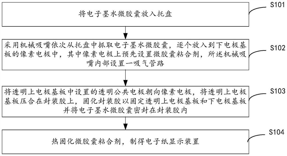
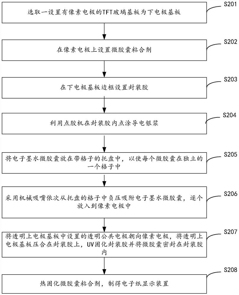
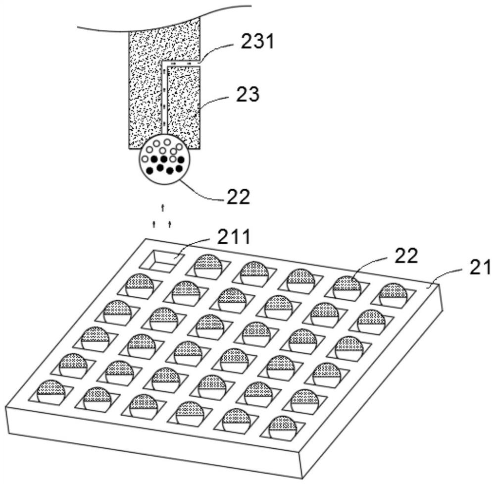
The invention relates to a manufacturing method and device of an electronic paper display device. The method comprises the following steps: putting the electronic ink microcapsule into a tray; a mechanical suction nozzle is adopted to sequentially grab the electronic ink microcapsules from the tray and put the electronic ink microcapsules into the pixel electrode of the lower electrode substrate one by one, microcapsule adhesives are arranged on the pixel electrode in advance, and an air suction pipeline is arranged in the mechanical suction nozzle; a transparent common electrode arranged in a transparent upper electrode substrate faces the pixel electrode, the transparent upper electrode substrate is pressed on the packaging adhesive, the packaging adhesive is cured to fix the transparent upper electrode substrate and the lower electrode substrate, and the electronic ink microcapsules are sealed in the packaging adhesive; and thermally curing the microcapsule adhesive to obtain the electronic paper display device. The problem of color display of the electronic paper can be solved, and the manufacturing process of the electronic paper display device is simplified.

Description

technical field [0001] The present invention relates to the technical field of display screens, and in particular, to a manufacturing method and device of an electronic paper display device. Background technique [0002] With the development of display technology, users have higher and higher requirements for display products. In recent years, a large number of new display technologies have emerged, such as electronic paper (Electronic Paper, E-paper) displays. [0003] The working principle of the electronic paper display device is that a plurality of display units arranged in an array are arranged on the oppositely arranged upper and lower substrates. In each display unit, the display layer includes charged particles (or a Charged particles (neutral particles) and electrolyte, the upper substrate and / or the lower substrate have electrode structures, and the electrode structures possessed by each display unit can generate an electric field. Under the action of the electric...

Claims


Application Information

Patent Timeline
Patent Type & Authority Applications(China)
IPC IPC(8): G02F1/167G02F1/1676G02F1/16757G02F1/1681
CPCG02F1/167G02F1/1676G02F1/16757G02F1/1681
Inventor 谢志生吴汝健李建华
Owner 广东志慧芯屏科技有限公司
Learn More