A magnetic resonance radio frequency coil adjustment method, magnetic resonance scanning system and medium
A technology of radio frequency coil and adjustment method, which is applied in the directions of using nuclear magnetic resonance image system for measurement, magnetic resonance measurement, and magnetic variable measurement, which can solve the problems that decoupling cannot be achieved by decoupling methods, achieve fast calculation speed, and enhance image information. Noise ratio, effect of improving decoupling efficiency
- Summary
- Abstract
- Description
- Claims
- Application Information
AI Technical Summary
Problems solved by technology
Method used
Image
Examples
Embodiment 1
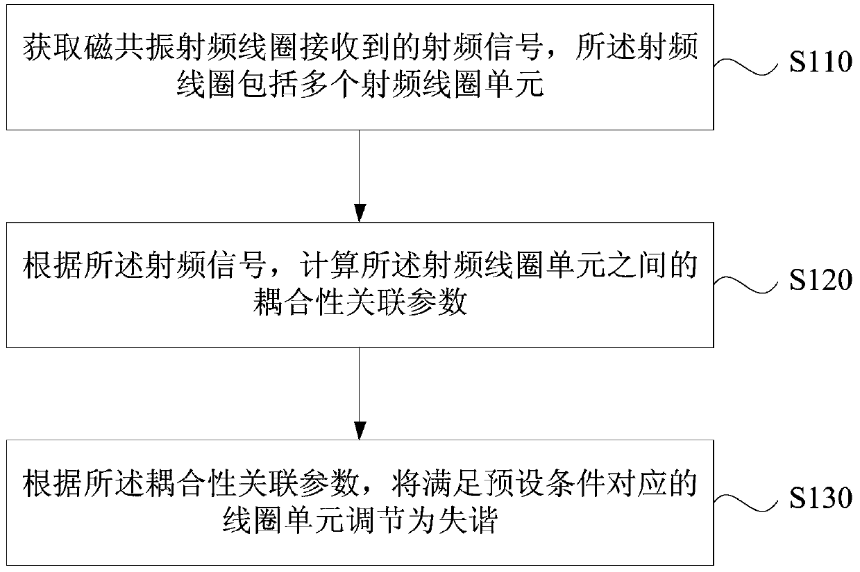
[0054] figure 1 It is a flow chart of a magnetic resonance radio frequency coil adjustment method provided by Embodiment 1 of the present invention. The technical solution of this embodiment may be applicable to the decoupling of the magnetic resonance coil unit. The method specifically includes the following operations:
[0055] S110. Acquire a radio frequency signal received by a magnetic resonance radio frequency coil, where the radio frequency coil includes a plurality of radio frequency coil units.
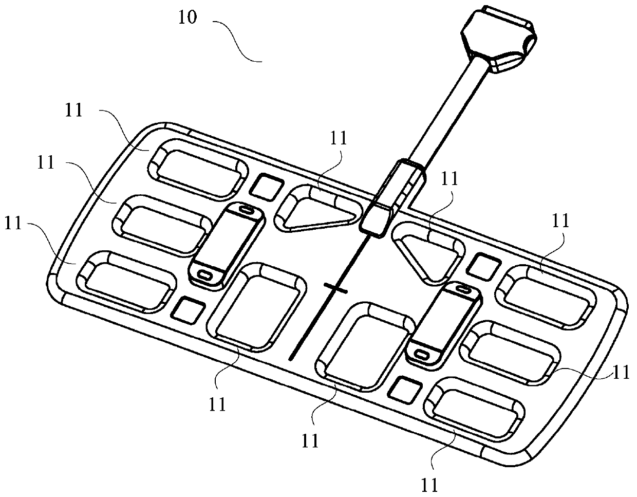
[0056] Radio frequency coils are widely used in nuclear magnetic resonance, and can be divided into flexible coils and fixed shell coils. Compared with fixed shell coils, flexible coils have the advantages of flexible use scenarios, tight coil fit, and high signal-to-noise ratio. figure 2It is a structural schematic diagram of a flexible coil, wherein the flexible coil 10 includes a plurality of coil units 11 arranged in an array. Multiple flexible coils can also be used...
Embodiment 2
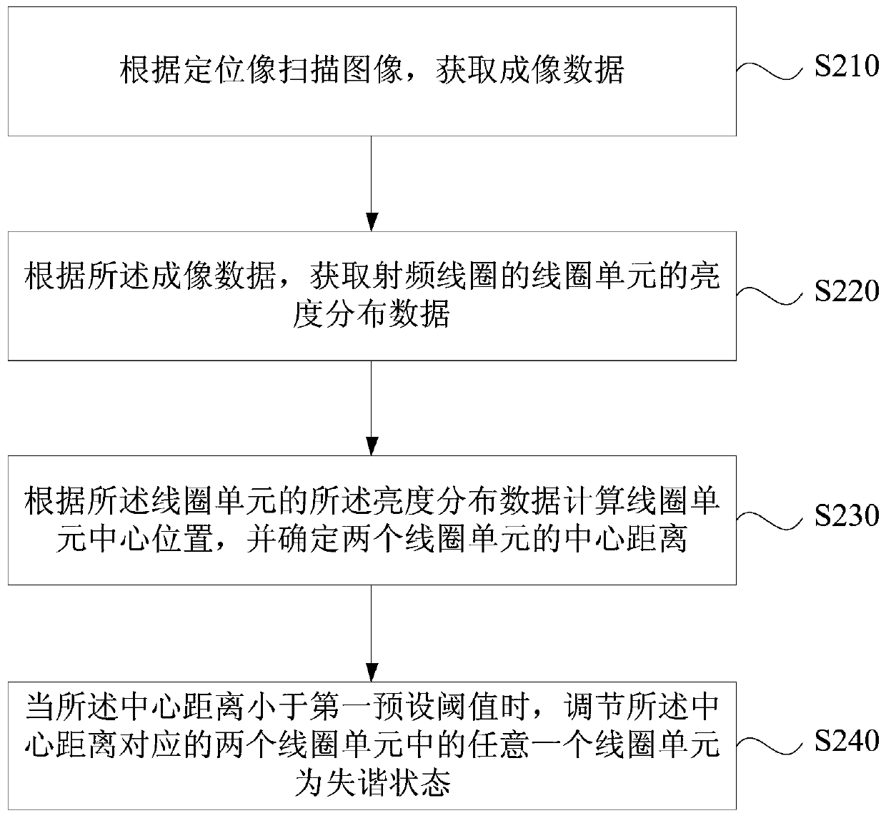
[0064] image 3 It is a flowchart of a method for adjusting a magnetic resonance radio frequency coil provided by Embodiment 2 of the present invention. In the technical solution of this embodiment, on the basis of the above embodiments, the radio frequency signal is specifically defined as imaging data; the coupling related parameter is specifically defined as the center distance between two coil units. Correspondingly, the method specifically includes the following operations:
[0065] S210. Scan the image according to the scout image to acquire imaging data.
[0066] In order to remove the coupling between the coil units, the embodiment of the present invention adopts scout scanning, which is performed to obtain the exact position of the lesion before scanning the lesion of the patient. Scout scans typically acquire sagittal, coronal, or cross-sectional images of the patient. The scout scan only needs to quickly scan to obtain the low-resolution image of the patient, and...
Embodiment 3
[0077] Figure 4 It is a flowchart of a method for adjusting a magnetic resonance radio frequency coil provided by Embodiment 3 of the present invention. In the technical solution of this embodiment, on the basis of any of the above embodiments, the radio frequency signal is specifically limited to noise data; the coupling correlation parameter is specifically limited to values of off-diagonal items in the noise correlation matrix. Correspondingly, the method specifically includes the following operations:
[0078] S310. Acquire noise data of the coil unit according to the noise pre-scan.
[0079] S320. Calculate a noise correlation matrix between coil units according to the noise matrix.
[0080] The noise pre-scan is a scan performed without a patient. The scan process is simple, and the noise data of each coil and each unit can be obtained. After obtaining the noise data of the coil units, the noise correlation matrix between the coil units can be calculated according ...
PUM
 Abstract
Description
Claims
Application Information
 - R&D
- Intellectual Property
- Life Sciences
- Materials
- Tech Scout
- Unparalleled Data Quality
- Higher Quality Content
- 60% Fewer Hallucinations
Browse by: Latest US Patents, China's latest patents, Technical Efficacy Thesaurus, Application Domain, Technology Topic, Popular Technical Reports.
© 2025 PatSnap. All rights reserved.Legal|Privacy policy|Modern Slavery Act Transparency Statement|Sitemap|About US| Contact US: help@patsnap.com


