
Vibration equipment confirmation method

A technology of vibration equipment and resonance frequency, applied in the field of vibration equipment confirmation, to achieve the effect of ensuring accuracy, small structural impact and convenient operation

Inactive Publication Date: 2017-11-17
GOERTEK INC
View PDF4 Cites 3 Cited by
  • Summary
  • Abstract
  • Description
  • Claims
  • Application Information

AI Technical Summary

Problems solved by technology

However, currently there is no equipment or instrumentation to test whether the shaking table is accurate

Method used


Image

  • Vibration equipment confirmation method
  • Vibration equipment confirmation method
  • Vibration equipment confirmation method

Examples


Embodiment Construction

[0029] In order to make the object, technical solution and advantages of the present invention clearer, the present invention will be further described in detail below in conjunction with the accompanying drawings and embodiments. It should be understood that the specific embodiments described here are only used to explain the present invention, not to limit the present invention.

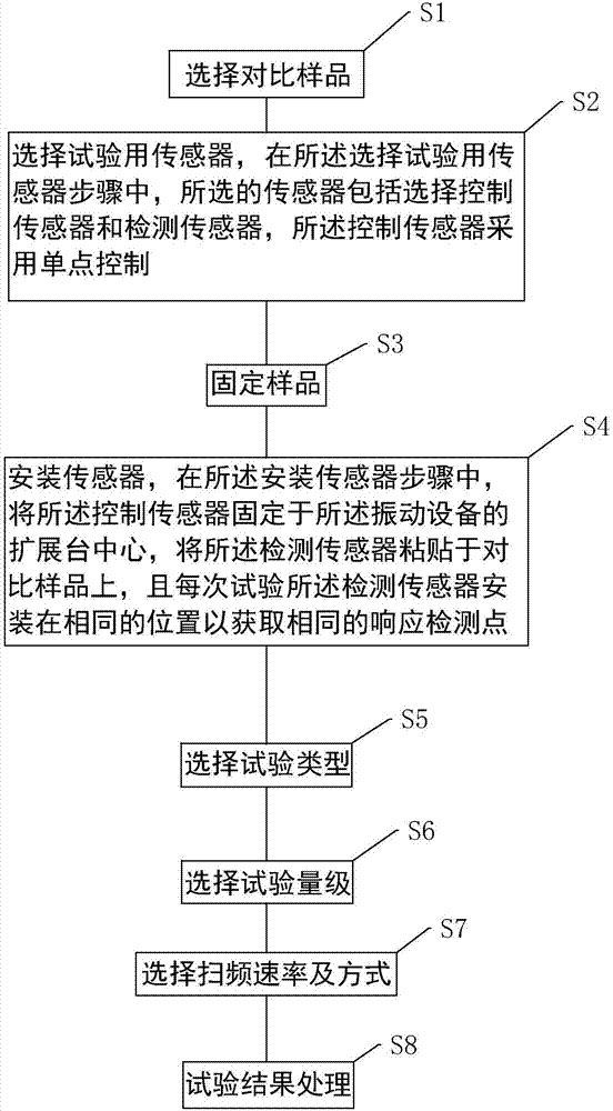
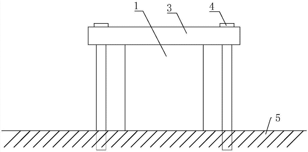
[0030] like figure 1 , figure 2 and image 3 As shown, a method for confirming vibration equipment includes the following steps: select a comparison sample, select a sensor for the test, fix the sample, install the sensor, select the test type, select the test magnitude, select the test video range, select the sweep rate and method and test result processing. In the method of the present invention, selected test sensor comprises control sensor and detection sensor 2, and control sensor adopts single-point control; On the comparison sample, and each test detection sensor 2 is installed in the s...


PUM


Abstract

The invention discloses a vibration equipment confirmation method comprising the following steps of selecting contrast samples, selecting sensors used for the test, fixing the samples, installing the sensors, selecting the test type, selecting the test magnitude, selecting the test video range, selecting the frequency sweep rate and mode and processing the test result. In the step of selecting the sensors used for the test, the selected sensors include a control sensor and a detection sensor, wherein the control sensor adopts single-point control. In the step of installing the sensors, the control sensor is fixed at the extension table center of vibration equipment, the detection sensor is adhered on the contrast samples, and the detection sensor is installed at the same position in each time of test. The method can be used for guiding inter-laboratory and intra-laboratory vibration capacity comparison, and the same response detection points are sampled in comparison so that the test data are ensured to be real and reliable, the vibration equipment is enabled to be accurately confirmed, and the method also has the advantages of being simple and practicable and convenient to operate.

Description

technical field [0001] The invention relates to the field of vibration equipment, in particular to a method for confirming vibration equipment. Background technique [0002] Vibration tables are usually used to test product performance, which simulates a series of controllable vibrations, including vibrations generated by natural or man-made environments. Place the product to be tested in a vibrating environment, and determine the product design and function requirements by testing whether the product can withstand the vibration environment test during transportation or use. The value of the vibrating table is to confirm the reliability of the product and effectively screen out defective products before leaving the factory to avoid damage on arrival and evaluate the failure analysis of the defective products to achieve a high-level, high-reliability product. [0003] Before the vibration table is used to test the reliability of the product, it must first be confirmed. Howe...

Claims


Application Information

Patent Timeline
IPC IPC(8): G01M7/02
CPCG01M7/02
Inventor 林俊龙
Owner GOERTEK INC
Learn More