
Fault fracture zone tunnel-section treatment structure in TBM construction tunnel

A broken zone and tunnel technology, which is applied in the field of poor geological conditions of TBM construction tunnels, can solve the problems of large excavation, delayed construction period, long construction period, etc. The effect of force and torque

Active Publication Date: 2017-11-17
CHINA HYDROELECTRIC ENGINEERING CONSULTING GROUP CHENGDU RESEARCH HYDROELECTRIC INVESTIGATION DESIGN AND INSTITUTE
View PDF12 Cites 13 Cited by
  • Summary
  • Abstract
  • Description
  • Claims
  • Application Information

AI Technical Summary

Problems solved by technology

[0004] The disadvantages of the existing technology mainly include: adopting the method of excavating first, and then dealing with the problems that arise, the TBM cutter head and shield are often stuck during the excavation, and the equipment is damaged, resulting in long-term shutdown, and it takes a long time to get out of trouble Due to the special body structure of the TBM, an advanced geological drilling rig equipped with it can only carry out drilling operations in a small area of ​​the top arch, making it impossible to carry out the advanced reinforcement treatment of the entire excavation section, resulting in treatment effects The drilling efficiency is poor, and the drilling efficiency is low, and the drilling operation will greatly occupy the construction period; in the excavation of large-diameter tunnels, the method of drilling and blasting excavation and TBM step-by-step method is adopted, and the excavation volume is extremely large, and the faults on site are broken. Excavation operations, tunnel slag discharge, and surrounding rock support are all very difficult, and the construction period is long, the cost is high, and the risk of personnel safety is high, so the advantages of TBM's rapid excavation and support cannot be fully utilized

Method used


Image

  • Fault fracture zone tunnel-section treatment structure in TBM construction tunnel
  • Fault fracture zone tunnel-section treatment structure in TBM construction tunnel
  • Fault fracture zone tunnel-section treatment structure in TBM construction tunnel

Examples


Embodiment Construction

[0025] The present invention is further described below by accompanying drawing.

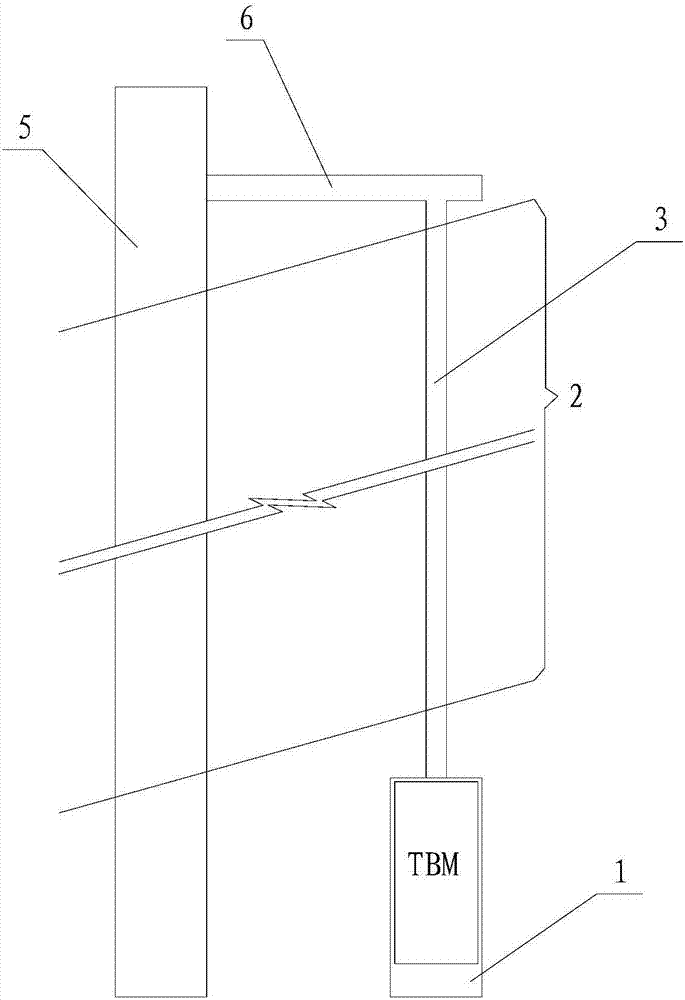
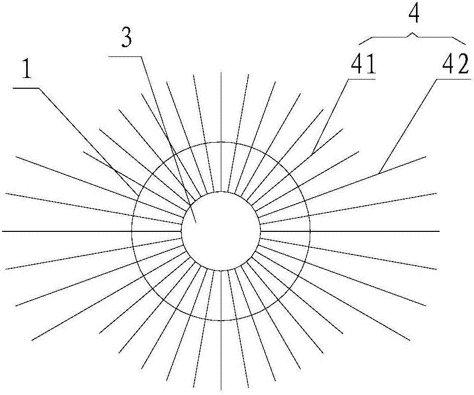
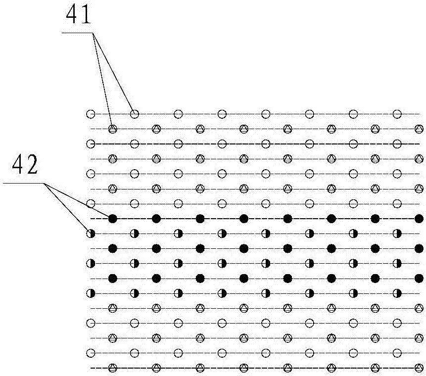
[0026] Such as figure 1 , figure 2 As shown, the present invention includes a tunnel 1 and a fault fracture zone 2 located in front of the face of the tunnel. A pilot tunnel 3 is provided in the center of the tunnel face. The pilot tunnel 3 is coaxial with the tunnel 1 and runs through the entire fault fracture zone 2. The surrounding rock of the pilot tunnel 3 is supported by shotcrete, and a plurality of grouting boreholes 4 are arranged on the surrounding rock. The end of the grouting boreholes 4 away from the center of the tunnel 1 exceeds the periphery of the tunnel 1 . Grouting material is provided in the borehole 4 . The diameter of the pilot tunnel 3 is generally set at 4-5m, and the drilling and blasting method can be used for excavation. The grouting hole 4 is set on the surrounding rock of the pilot tunnel 3, and the purpose of filling the grouting hole 4 with grouting material is ...


PUM


Abstract

The invention discloses a fault fracture zone tunnel-section treatment structure in a TBM construction tunnel and a treatment method in the technical field of treatment of TBM construction tunnel unfavorable geological conditions. The fault fracture zone tunnel-section treatment structure comprises a tunnel and a fault fracture zone located in front of a tunnel face. A pilot tunnel is formed in the center of the tunnel face, the extending direction of the pilot tunnel is consistent with the extending direction of the tunnel, and the pilot tunnel penetrates through the whole fault fracture zone; and a pilot tunnel surrounding rock is retained and protected by sprayed concrete, a plurality of grouting drill holes are formed in the surrounding rock, one ends, away from the center of the tunnel, of the grouting drill holes exceed the periphery of the tunnel, and grouting materials are arranged in the grouting drill holes. According to the fault fracture zone tunnel-section treatment structure in the TBM construction tunnel and the treatment method, the mode that the fault fracture zone is firstly reinforced and then tunneled is adopted, the fault fracture zone is changed to be a relatively stable area and then subjected to TBM tunneling, and the characteristics of TBM rapid tunneling and retaining and protecting are fully developed; and compared with an existing treatment structure or method, the fault fracture zone tunnel-section treatment structure and the treatment method are higher in efficiency, safer in operation and lower in cost, and have good social and economic benefits.

Description

technical field [0001] The invention relates to the technical field of treatment of unfavorable geological conditions in TBM construction tunnels, in particular to a treatment structure and treatment method for fault fracture zones of TBM construction tunnels. Background technique [0002] Due to its advantages of high excavation efficiency, good construction quality, and little disturbance to surrounding rock, TBM has been widely used in water conservancy and hydropower engineering, rail transit and other industries in recent years. Poor adaptability to adverse geological conditions such as broken zones. TBM excavation efficiency is low in the fault fracture zone, and problems such as TBM cutter head and shield being stuck and equipment damage may be caused by the deformation and collapse of the surrounding rock in the tunnel. The long-term jamming treatment and equipment repair will also be delayed in the later period. Due to the low strength of the rock mass in the fault...

Claims


Application Information

Patent Timeline
Patent Type & Authority Applications(China)
IPC IPC(8): E21D9/06E21D9/08E21D11/10
CPCE21D9/0607E21D9/08E21D11/10Y02E10/20
Inventor 胡亚东张世殊彭仕雄崔中涛姚林林
Owner CHINA HYDROELECTRIC ENGINEERING CONSULTING GROUP CHENGDU RESEARCH HYDROELECTRIC INVESTIGATION DESIGN AND INSTITUTE
Learn More