
Glove weaving device

A glove and machine head technology, which is applied to weft knitting, knitting, and circular knitting machines with individual moving needles. It can solve the problems of difficult assembly, high labor costs, and complicated operations, and achieve increased knitting speed. , Reduce labor costs, simple and reliable structure

Active Publication Date: 2017-11-17
Zhejiang Baixiang Technology Co Ltd
View PDF6 Cites 9 Cited by
  • Summary
  • Abstract
  • Description
  • Claims
  • Application Information

AI Technical Summary

Problems solved by technology

Because there are many parts, the structure is more complicated, the assembly is difficult, and the labor cost is high; in addition, the traditional glove machine also has problems such as low efficiency and difficult troubleshooting;
[0004] 2) The density adjustment device of the glove machine is generally manually adjusted. The worker needs to use a screwdriver to loosen the screw, and then manually adjust the density knob (rotation adjustment). The specific adjustment range (rotation angle) depends entirely on the experience of the operator. Complicated, low adjustment accuracy and other issues;
[0005] 3) The needle selection device of the glove machine generally adopts roller needle selection, and the roller needle selection is to arrange pins on the needle drum. When the knitting shape or color of the gloves needs to be changed, the arrangement method needs to be changed again, which has defects such as complicated operation, high cost, and single color of the woven gloves;
Repeated measurement and adjustment in this way, the process is complicated and the weaving efficiency is low

Method used


Image

  • Glove weaving device
  • Glove weaving device
  • Glove weaving device

Examples


Embodiment Construction

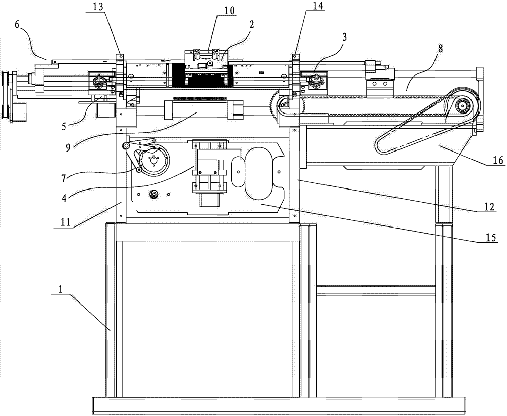
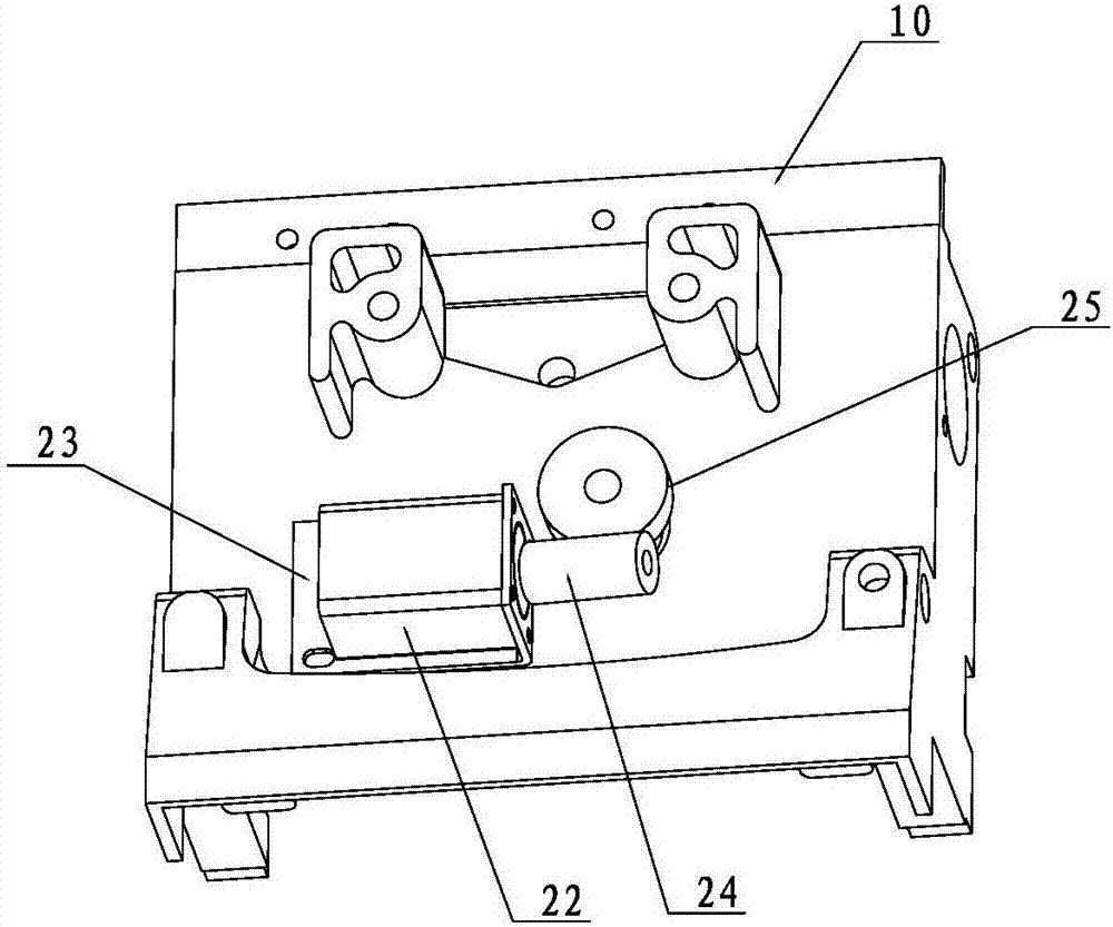
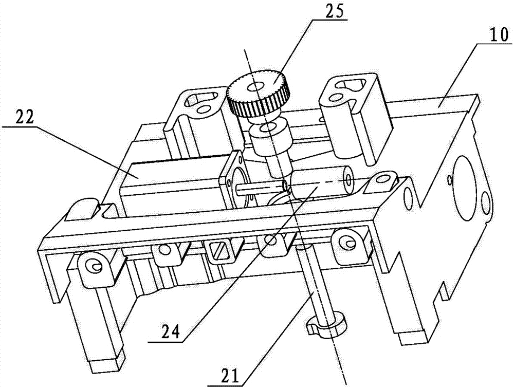
[0038] Such asfigure 1 As shown, a glove knitting device includes a frame 1, an automatic density adjustment mechanism 2 arranged on the frame 1, a push rod control mechanism 3, a glove length detection mechanism 4, a scissors transmission mechanism 5, a fork knife transmission mechanism 6, Cam transmission mechanism 7, machine head transmission mechanism 8, needle selection mechanism 9, and a control unit for controlling the above-mentioned various mechanisms; wherein, a left wall panel 11 and a right wall panel 12 are respectively provided on the left and right sides of the top of the frame 1 , A left corner wallboard 13 and a right corner wallboard 14 are arranged above the left wallboard 11 and the right wallboard 12 respectively. Generally, the glove knitting device has two sets of knitting systems, front and back, and knits both sides of the glove at the same time. Each knitting system is equipped with its own machine head 10, automatic density adjustment mechanism 2, ej...


PUM


Abstract

The invention discloses a glove weaving device. The glove weaving device comprises a device frame, an automatic density adjustment mechanism, an ejector rod control mechanism, a glove length detecting mechanism, a scissor driving mechanism, a fork knife driving mechanism, a cam driving mechanism, a device head driving mechanism, a needle selecting mechanism and a control unit, wherein the automatic density adjustment mechanism is installed on a device head, the ejector rod control mechanism, the scissor driving mechanism and the fork knife driving mechanism are installed on sharp corner wall boards of the device frame and used for controlling movement of ejector rods, scissors and a fork knife respectively, the glove length detecting mechanism and the cam driving mechanism are installed on a rear wall board of the device frame, and the needle selecting mechanism is installed below a needle plate and used for selecting needles; the device head driving mechanism is installed on a box of the device frame and used for controlling movement of the device head. With the glove weaving device, gloves can be woven and measured in a full-automatic mode; through a motor, all the mechanisms are driven to act, the structure is concise and reliable, assembling is convenient, operation is stable, and the maintenance rate is low.

Description

technical field [0001] The invention relates to a knitting device, in particular to a glove knitting device. Background technique [0002] The glove machine is a device for knitting gloves. The glove machines currently on the market generally have the following problems: [0003] 1) Most of them adopt mechanical transmission, and the movement of each component of the glove machine is realized through gear and rack meshing, clutch control, chain, slider transmission, three-phase motor, etc. Because there are many parts, the structure is more complicated, the assembly is difficult, and the labor cost is high; in addition, the traditional glove machine also has problems such as low efficiency and difficult troubleshooting; [0004] 2) The density adjustment device of the glove machine is generally manually adjusted. The worker needs to loosen the screw with a screwdriver, and then manually adjust the density knob (rotation adjustment). The specific adjustment range (rotation a...

Claims


Application Information

Patent Timeline
Patent Type & Authority Applications(China)
IPC IPC(8): D04B9/58D04B9/38D04B15/60
CPCD04B9/38D04B9/58D04B15/60
Inventor 陈百祥冯建明
Owner Zhejiang Baixiang Technology Co Ltd
Learn More