
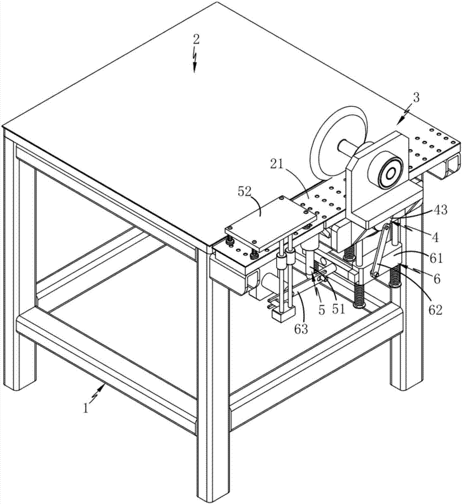
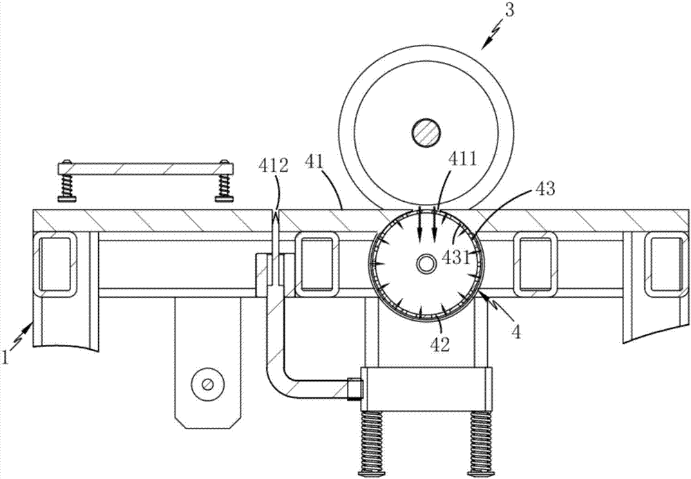
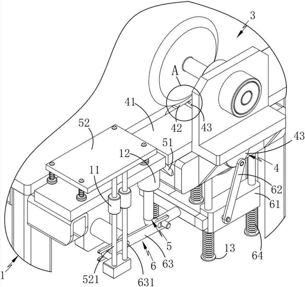
Casting film cutting edge material smashing device

A processing device and casting film technology, which is applied in metal processing and other directions, can solve the problems of unrealistic chip processing methods, and achieve the effects of efficient and fast processing, neat cutting, and reasonable structure.

Inactive Publication Date: 2017-11-17
湖州精特新材料有限公司
View PDF1 Cites 1 Cited by
  • Summary
  • Abstract
  • Description
  • Claims
  • Application Information

AI Technical Summary

Problems solved by technology

[0004] The above technical solution supplies liquid to the chips, and after the liquid is mixed with the chips, the chips are combined with the film or side material while the liquid evaporates, so as to eliminate the pollution of the chips to the production and the environment; however, the transparency and surface requirements of the film are relatively high. In the case of high shavings, the chip treatment method of the invention cannot be realized. In addition, at this stage, the control of production costs is becoming more and more important, so the available production waste is eager to use. There is an urgent demand for cutting production equipment for subsequent use

Method used


Image

  • Casting film cutting edge material smashing device
  • Casting film cutting edge material smashing device
  • Casting film cutting edge material smashing device

Examples


Embodiment 1

[0037] Such as figure 1 , 2 , 3, 4, 5 and 6, a cast film cutting trim processing device, including a frame 1, fixedly installed on the frame 1 to carry out trim 21 shears on the cast film 2 The cutting assembly 3 also includes a support assembly 4, a crushing assembly 5, and a transmission assembly 6. The support assembly 4 is fixedly arranged on the frame 1 and is located below the side material 21, and it includes a support for carrying out the transmission support of the side material 21. Plate 41, a hollow adsorption cavity 42 fixedly arranged under the support plate 41, and a transfer roller 43 rotatably mounted inside the adsorption cavity 42 for linear transmission of the side material 21, the transfer roller 43 is hollow, and after setting A plurality of adsorption holes 431 on its outer peripheral surface carry out the adsorption and transmission of the side material 21; the crushing assembly 5 includes a pulverizing blade 51 which passes through the support plate 41...

Embodiment 2

[0039]The inventor believes that in order to better implement the technical solution, further specific implementation methods are necessary, so the inventor describes the second embodiment on the basis of the first embodiment.

[0040] Such as figure 1 , 2 , 3, 4, 5 and 6, a cast film cutting trim processing device, including a frame 1, fixedly installed on the frame 1 to carry out trim 21 shears on the cast film 2 Cut component 3, also includes:

[0041] The support assembly 4, the support assembly 4 is fixedly arranged on the frame 1 and is located below the edge material 21, which includes a support plate 41 for supporting the edge material 21 transmission, fixedly arranged under the support plate 41 and is The suction chamber 42 arranged in hollow and the conveying roller 43 which is installed in the interior of the suction chamber 42 to carry out the linear transmission of the side material 21, the conveying roller 43 is set in hollow, and the side material is carried o...


PUM


Abstract

The invention relates to a cast film cutting edge material crushing device, which includes a frame, a shearing assembly, a support assembly, a crushing assembly and a transmission assembly, and the support assembly is fixedly arranged on the frame and located below the edge material, which includes The supporting plate and the conveying roller set in hollow carry out the adsorption and transmission of the side material through a number of adsorption holes opened on its outer peripheral surface; the crushing assembly includes a crushing blade and a pressing plate assembly that is linked and matched with the crushing blade; the linkage assembly includes an up and down sliding device The moving block, the first connecting rod and the second connecting rod, the two ends of the second connecting rod are respectively connected with the crushing blade and the pressing plate assembly; the side material is adsorbed and fixed by the conveying roller with adsorption capacity, and at the same time, it is synchronized with the film Conveying and collecting swarf at the same time. In addition, the rotation of the conveying roller realizes the neat cutting of the edge material, realizes the cutting, chip collection and edge material finishing of the cast film, and solves the technical problems of the edge material cutting and processing part in the cast film industry.

Description

technical field [0001] The invention relates to the technical field of casting film auxiliary material processing equipment, in particular to a casting film cutting edge material crushing device. Background technique [0002] In the manufacturing process of various polymer films, due to their production requirements, the deformed or damaged parts of the side ends after being clamped or fixed need to be cut. The cutting in the conveying direction of the film is mostly carried out by various cutting blades. Micro film scraps are produced in the process, and the film scraps are not only attached to the device for cutting, but also attached to the film, thereby polluting the film, device and the environment; Separated from the finished film, the subsequent use of the offcut film takes a lot of time to cut and process, which consumes a lot of manpower and material resources and increases the production cost. [0003] A film cutting method and device disclosed in Chinese inventio...

Claims


Application Information

Patent Timeline
IPC IPC(8): B26D1/08B26D7/01B26D5/08
CPCB26D1/085B26D5/08B26D7/015
Inventor 徐婷
Owner 湖州精特新材料有限公司
Learn More