U-shaped steel bar bender

A steel bar bending and U-shaped technology, which is applied in the field of bending machines, can solve problems that affect the progress of the project, consume manpower and time, and achieve the effect of ensuring the progress of the project

Inactive Publication Date: 2017-11-14
沈军
View PDF5 Cites 4 Cited by
  • Summary
  • Abstract
  • Description
  • Claims
  • Application Information

AI Technical Summary

Problems solved by technology

[0002] With the continuous improvement of people's living standards, people's requirements for housing are also increasing, and people have begun to move into tall buildings. In order to meet people's housing needs, construction developers have begun to build tall communities to meet people's needs; When building a building, it is necessary to lay the foundation and build the load-bearing wall of the house. When building the load-bearing wall, it needs to be cast with concrete and steel cages. During the pouring process, sometimes the steel bars need to be bent according to the needs of the project; Workers use hammers to beat and bend. When a large number of steel bars need to be bent, it takes a lot of manpower and time, which greatly affects the progress of the project.

Method used


Image

  • U-shaped steel bar bender

Examples


Embodiment Construction

[0012] The present invention will be further described below in conjunction with accompanying drawing:

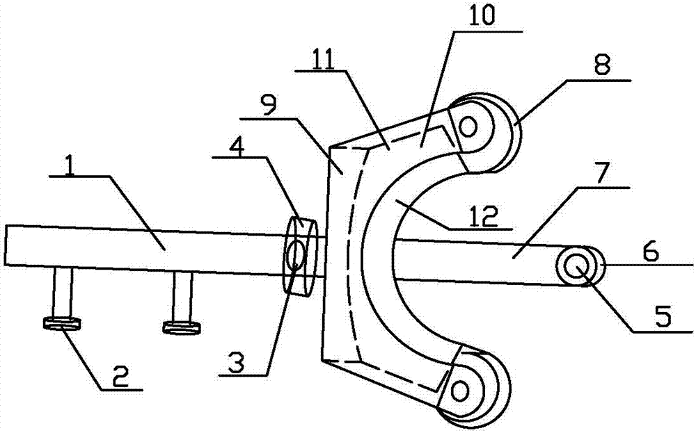
[0013] like figure 1 Shown, the technical scheme that the present invention takes is as follows:

[0014] U-shaped steel bar bending machine, including electric hydraulic oil pump 1, threaded joint 2, inner hexagonal screw 3, flange 4, bottom plate fixing column 5, concave wheel 6, fixed bottom plate 7, rolling wheel 8, U-shaped module 11; the U The U-shaped module 11 is composed of a support plate 9, an upper U-shaped plate 10, and a lower U-shaped plate 12. The support plate 9 is sandwiched between the upper U-shaped plate 10 and the lower U-shaped plate 12 to form a complete U-shaped module 11. The support plate 9 It is in the shape of a cuboid, the upper U-shaped plate 10 and the lower U-shaped plate 12 are parallel to each other, the distance between the upper U-shaped plate 10 and the lower U-shaped plate 12 is consistent with the width of the support plate 9, the up...


PUM


Abstract

The invention discloses a U-shaped steel bar bender which comprises an electric hydraulic oil pump, threaded connectors, a hexagon socket head cap screw, a flange, a bottom plate fixing pillar, a U-shaped wheel, a fixing bottom plate, rolling wheels and a U-shaped module. By means of the U-shaped steel bar bender, the U-shaped steel bar bender can bend steel bars easily in the range from 0 degree to 180 degrees according to engineering needs; and when a large number of steel bars need to be bent, the U-shaped steel bar bender can complete bending easily within short time, a large amount of labor and time do not need to be consumed, and the project progress is ensured.

Description

technical field [0001] The invention relates to a bending machine, in particular to a U-shaped steel bar bending machine. Background technique [0002] With the continuous improvement of people's living standards, people's requirements for housing are also increasing, and people have begun to move into tall buildings. In order to meet people's housing needs, construction developers have begun to build tall communities to meet people's needs; When building a building, it is necessary to lay the foundation and build the load-bearing wall of the house. When building the load-bearing wall, it needs to be cast with concrete and steel cages. During the pouring process, sometimes the steel bars need to be bent according to the needs of the project; At that time, workers used iron hammers to beat and bend. When a large number of steel bars needed to be bent, it took a lot of manpower and time, which greatly affected the progress of the project. Contents of the invention [0003] ...

Claims


Application Information

Patent Timeline
Patent Type & Authority Applications(China)
IPC IPC(8): B21F1/00
CPCB21F1/004
Inventor 沈军
Owner 沈军
Why Eureka
Try Eureka