
Double-sleeve steel-structure beam-column joint and installation method

A beam-column joint and steel structure technology, which is applied in building construction, building material processing, construction, etc., can solve the problems of high destructiveness of building structure and difficult to restore quickly, so as to improve the seismic performance, and the joint force is reasonable and clear. , Improve the effect of welding connection

Active Publication Date: 2017-11-10
QINGDAO TECHNOLOGICAL UNIVERSITY
View PDF19 Cites 29 Cited by
  • Summary
  • Abstract
  • Description
  • Claims
  • Application Information

AI Technical Summary

Problems solved by technology

[0005] The invention solves the problem that the earthquake is very destructive to the building structure and it is difficult to recover quickly by cleverly setting multi-level energy consumption points

Method used


Image

  • Double-sleeve steel-structure beam-column joint and installation method
  • Double-sleeve steel-structure beam-column joint and installation method
  • Double-sleeve steel-structure beam-column joint and installation method

Examples


Embodiment 1

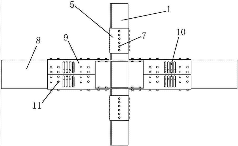
[0052] Such as Figure 1-3As shown, a double-sleeve steel structure beam-column joint includes a steel pipe column 1 and a steel beam 8, and also includes an inner sleeve steel pipe 2, a circular sleeve 4, a rectangular sleeve 5, a conversion connecting plate, and an energy-dissipating steel plate 9, Short beam 14 and ratchet connector 13, threaded hole 3 is provided on inner sleeve steel pipe 2, bolt hole 6 is provided on circular sleeve 4, rectangular sleeve 5 and steel pipe column 1, inner sleeve steel pipe, circular sleeve, rectangular sleeve The tube and the steel pipe column are connected by long bolts 7, and the steel pipe column is also connected with the conversion connection plate, and the two sides of the conversion connection plate are respectively connected with the short beam 14 through the upper and lower U-shaped energy-dissipating steel plates 9, and the short beam is also connected through the upper and lower The U-shaped energy-dissipating steel plate and th...

Embodiment 2

[0070] The structure of this embodiment is basically the same as that of Embodiment 1, as Figure 15 As shown, the difference is that the cross-section shape of the upper and lower energy-dissipating combined steel plates is a "one"-shaped structure, which is more convenient for on-site installation, and the rest are the same as in Embodiment 1.

Embodiment 3

[0072] The structure of this embodiment is basically the same as that of Embodiment 1, as Figure 16 As shown, the difference is that the section shape of the upper and lower energy-dissipating combined steel plates is L-shaped, which is more convenient for on-site installation, and the rest are the same as in Embodiment 1.

[0073] According to actual needs, there are many combinations of assembled ratchet energy-dissipating double-sleeve steel structure beam-column joints, such as Figure 17-18 shown. The connection method in the present invention can also be used for side columns and side columns of prefabricated structures, and the application range is enlarged.


PUM


Abstract

The invention relates to the technical field of structural engineering, in particular to a double-sleeve steel-structure beam-column joint and an installation method. The double-sleeve steel-structure beam-column joint comprises steel pipe columns and steel beams and further comprises inner sleeved steel pipes, circular sleeves, rectangular sleeves, a transfer connecting plate, energy dissipation steel plates, short beams and ratchet wheel connecting pieces, threaded holes are formed in the inner sleeved steel pipes, and bolt holes are formed in the circular sleeves, the rectangular sleeves and the steel pipe columns; and the inner sleeved steel pipes, the circular sleeves, the rectangular sleeves and the steel pipe columns are connected through long bolts, the steel pipe columns are further connected with the transfer connecting plate, the upper and lower sides of the transfer connecting plate are connected with the short beams through the upper energy dissipation steel plates and the lower energy dissipation steel plates correspondingly, and the short beams are further connected with the steel beams through the upper and lower energy dissipation steel plates and the ratchet wheel connecting pieces. According to the double-sleeve steel-structure beam-column joint and the installation method, by arranging multi-stage energy dissipation points ingeniously, the problems that the destructive effect of an earthquake on a building structure is large, and the building structure is difficult to recover rapidly are solved; and the joint columns are connected by adopting the core pipes, the double-sleeves and the long bolts, the bearing capacity is superior to the bearing capacity of an existing beam-column joint mode, and the shear capacity of the whole joint is enhanced.

Description

technical field [0001] The invention relates to the technical field of structural engineering, in particular to an assembled ratchet energy-dissipating double-sleeve steel structure beam-column node based on a ratchet mechanism, an energy-dissipating steel plate and a double-sleeve connection design and an installation method. Background technique [0002] Steel structure buildings have the characteristics of high strength, light weight, fast construction speed, good seismic performance and high degree of industrialization. Steel structural components form a structural system by connecting nodes, and the choice of node form has a direct impact on structural integrity, reliability, construction period, and the design and construction of auxiliary components. [0003] Steel structure nodes mainly realize the splicing and connection of beams, columns, supports and other components. Existing steel structure nodes have various forms, which can be divided into rigid joints, hinge...

Claims


Application Information

Patent Timeline
IPC IPC(8): E04B1/58E04G21/14
CPCE04B1/2403E04B2001/2406E04G21/14
Inventor 牟犇张春巍王君昌王清华杨爱青赵勇
Owner QINGDAO TECHNOLOGICAL UNIVERSITY
Learn More