Electricity equipment

An electrical equipment and screw-shaped technology, applied in the field of electrical equipment, can solve the problems of board deviation, poor bonding strength of electrical boards, waste of manpower and material resources, etc., so as to reduce the waste of manpower and material resources, remove it conveniently and quickly, and increase work efficiency. Effect

Inactive Publication Date: 2017-11-10
益福光(天津)电子科技有限公司
View PDF3 Cites 0 Cited by
  • Summary
  • Abstract
  • Description
  • Claims
  • Application Information

AI Technical Summary

Problems solved by technology

[0002] The electrical board is a commonly used power facility. The electrical board is mainly composed of an anti-rust board and an insulating board that are pressed and consolidated into one body. The production efficiency is low, the pressing force is uneven, the bonding strength of the electrical board is poor, manpower and material resources are wasted, and the flatness and aesthetics of the pressing are not guaranteed. The use of a compacting machine is usually to pass a board through the lock first. Fix it, and then use a compacting machine to press down on the other board. This method of compaction will easily cause the pressed board to deviate during the pressing process, and after the compaction is formed, remove the formed board. It is necessary to manually open the lock when the electrical board is used. The operation steps are cumbersome and very inconvenient to use, which greatly reduces the efficiency of the pressing and forming of the electrical board.

Method used


Image

  • Electricity equipment
  • Electricity equipment
  • Electricity equipment

Examples


Embodiment Construction

[0021] The preferred embodiments of the present invention will be described in detail below in conjunction with the accompanying drawings, so that the advantages and features of the present invention can be more easily understood by those skilled in the art, so as to define the protection scope of the present invention more clearly.

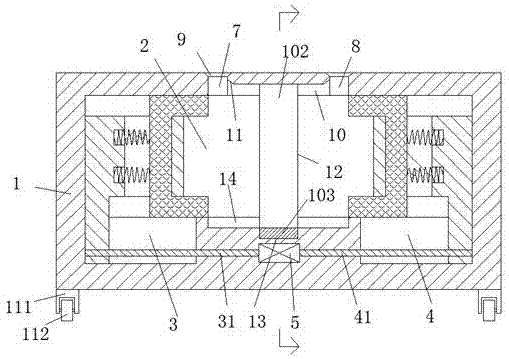
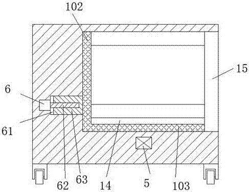
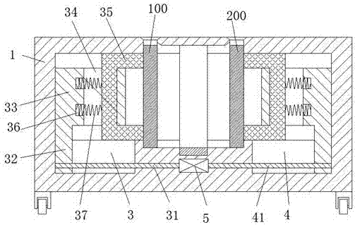
[0022] refer to Figure 1-5 The shown electric equipment includes a casing 1, a foot rod 111 is fixedly installed on the bottom of the casing 1, and a roller 112 is rotatably installed on the bottom of the foot rod. Hollow chamber 2, the left and right ends of the bottom end of the hollow chamber 2 are respectively mutually called with a left sliding groove 3 and a right sliding groove 4, and all the gaps between the left sliding groove 3 and the right sliding groove 4 The housing 1 is provided with a first motor 5, and the left sliding groove 3 and the right sliding groove 4 are respectively mutually symmetrically provided with a left screw rod ...


PUM


Abstract

The present invention discloses electricity equipment, which comprises a shell, wherein foot rods are fixedly arranged on the bottom portion of the shell, the bottom portions of the foot rods are rollingly provided with rollers, a hollow cavity capable of extending left and right is arranged in the shell, the left end and the right end on the bottom end portion of the hollow cavity are respectively and symmetrically provided with a left sliding movement groove and a right sliding movement groove, a first motor is arranged in the shell between the left sliding movement groove and the right sliding movement groove, and a left screw rod and a right screw rod are respectively and symmetrically arranged in the left sliding movement groove and the right sliding movement groove, and are respectively provided with a left pressing fixation device and a right pressing fixation device in a matched manner. According to the present invention, the structure of the pressing fixation apparatus is simple, the production cost is low, the operation is simple and convenient, the working efficiency of the electric board pressure fixing molding is substantially increased while the waste of labor and material resources is reduced, the electric board being subjected to the pressure fixing molding is firm and reliable and is convenient and rapid to remove, and the flatness and the beautiful degree of the electric board are effectively improved.

Description

technical field [0001] The invention relates to the field of electric power, in particular to electric equipment. Background technique [0002] The electrical board is a commonly used power facility. The electrical board is mainly composed of an anti-rust board and an insulating board that are pressed and consolidated into one body. The production efficiency is low, the pressing force is uneven, the bonding strength of the electrical board is poor, manpower and material resources are wasted, and the flatness and aesthetics of the pressing are not guaranteed. The use of a compacting machine is usually to pass a board through the lock first. Fix it, and then use a compacting machine to press down on the other board. This method of compaction will easily cause the pressed board to deviate during the pressing process, and after the compaction is formed, remove the formed board. It is necessary to manually open the lock when using the electrical board. The operation steps are cu...

Claims


Application Information

Patent Timeline
Patent Type & Authority Applications(China)
IPC IPC(8): B32B37/10
CPCB32B37/10
Inventor 姚瑞波
Owner 益福光(天津)电子科技有限公司
Why Eureka
Try Eureka