


Quick Research
Generate reliable direction feasibility study reports for your R&D in just a few steps.

Technical Q&A
Discover and master advanced knowledge NOW. Basics, ideas, possibilities, all at once.

Find Solutions
As an expert in R&D theories, this can generate solutions to your technical problems instantly.

Evaluate Feasibility
Analyze your overall solution with one click, know your potential R&D risks in advance.

Monitor Landscape
Get weekly tech updates, stay abreast of the latest tech innovations and key insights.
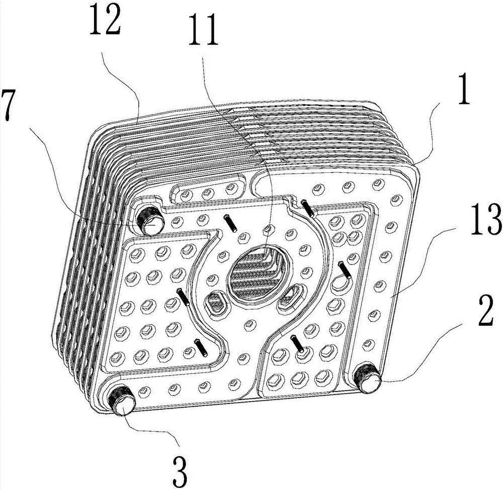
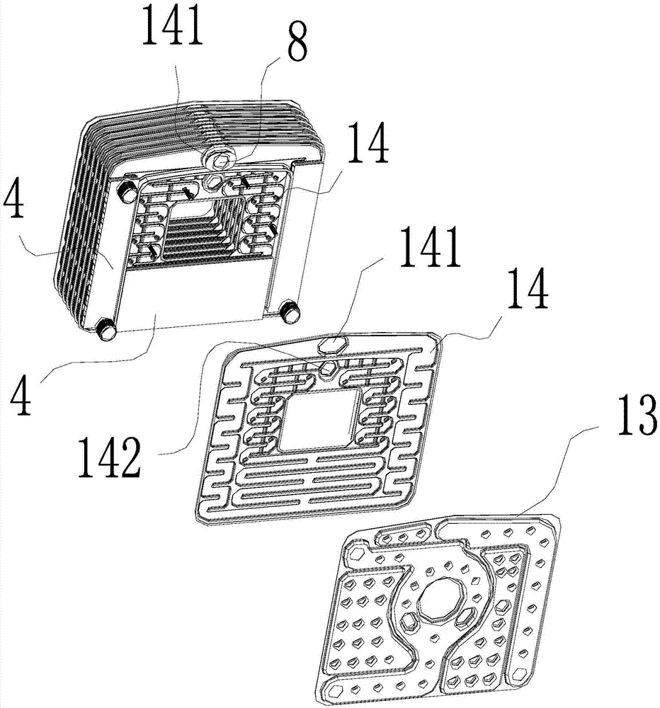
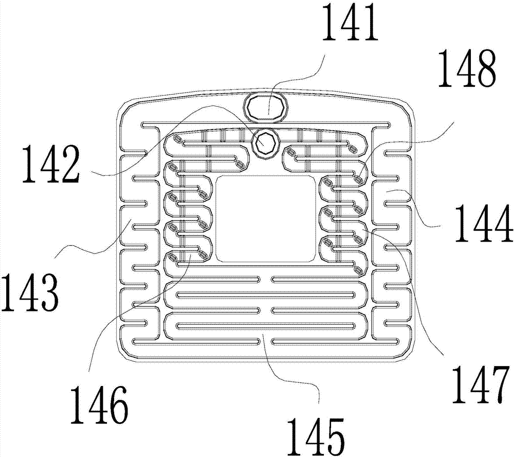
Purifying, high-pressure gas-supplying and detouring combustion heat exchanger
A heat exchanger and burner technology is applied in the field of purifying high-pressure air supply bypass combustion heat exchangers, which can solve the problems of complex structure, complex manufacturing process, and difficult cleaning of the heat exchanger, and achieves no need to dismantle and clean, and has a wide range of applications. , the effect of practicality
- Summary
- Abstract
- Description
- Claims
- Application Information
AI Technical Summary
Problems solved by technology
Method used
Image

Examples
Embodiment Construction
[0023] Embodiments of the present invention are described in detail below, examples of which are shown in the drawings, wherein the same or similar reference numerals represent the same or similar elements or elements having the same or similar functions throughout.
[0024] The orientations shown in the drawings should not be construed as limiting the specific protection scope of the present invention, but are only for reference and understanding of preferred embodiments, and the product components shown in the drawings can be changed in position or increased in number or simplified in structure.
[0025] The "connection" described in the specification and the "connection" relationship between the parts shown in the drawings can be understood as fixed connection or detachable connection or integral connection; it can be directly connected or connected through an intermediary. A person of ordinary skill in the art can understand the connection relationship according to the spec...
PUM
 Abstract
Description
Claims
Application Information
 - R&D Engineer
- R&D Manager
- IP Professional
- Industry Leading Data Capabilities
- Powerful AI technology
- Patent DNA Extraction
Browse by: Latest US Patents, China's latest patents, Technical Efficacy Thesaurus, Application Domain, Technology Topic, Popular Technical Reports.
© 2024 PatSnap. All rights reserved.Legal|Privacy policy|Modern Slavery Act Transparency Statement|Sitemap|About US| Contact US: help@patsnap.com