
Novel re-beaming machine feeding device

A new type of conveying device technology, applied in the field of feeding devices of new parallel shaft machines, can solve the problems of hidden safety hazards, low work efficiency, inconvenient feeding, etc., and achieves low production process requirements, simple structure, and extended service life. Effect

Inactive Publication Date: 2017-11-07
湖州市长兴隆昌丝绸有限公司
View PDF9 Cites 1 Cited by
  • Summary
  • Abstract
  • Description
  • Claims
  • Application Information

AI Technical Summary

Problems solved by technology

[0002] The shaft paralleling machine is a device that evenly combines multiple wires together. The wires are usually wound on the rollers. Before the shafts are combined, multiple rollers wrapped with wires need to be placed on the feeding frame. At present, manual handling is usually used. , or the way of forklift handling to place and load materials, because the roller shaft is very heavy, it is difficult to carry, the work efficiency is low, the material is not convenient to load, and there are potential safety hazards

Method used


Image

  • Novel re-beaming machine feeding device
  • Novel re-beaming machine feeding device
  • Novel re-beaming machine feeding device

Examples


Embodiment 1

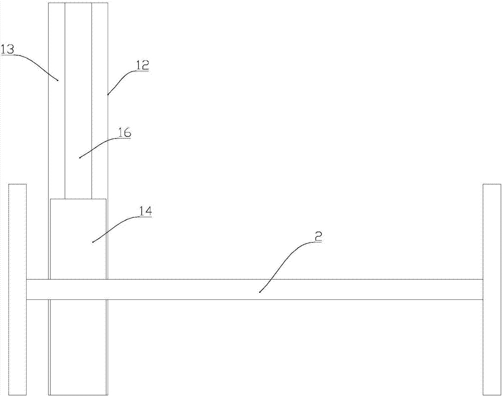
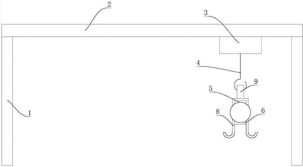
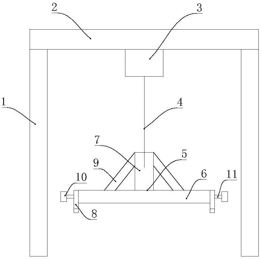
[0021] Such as Figure 1-5 As shown in the figure, a new type of feeding device for the parallel shaft machine, including a sliding plate conveying device and a driving feeding device;

[0022] The crane feeding device includes four vertical bottom brackets 1, an I-shaped top bracket 2, and a crane 3 arranged on the top bracket 2, and a hanger 5 is hung on the hook 4 of the crane 3 The hanger 5 includes a horizontal bar 6 and a vertical bar 7 fixed above the middle of the bar 6. The vertical bar 7 is provided with a hook hole matching the hook 4. The two ends of the bar 6 are respectively welded with a "several"-shaped hook 8, and the cross bar 6 is embedded in the bottom groove of the hook 8.

[0023] The slide conveying device includes a rail groove 12 arranged below the driving feeding device, a pair of rails 13 are arranged in the rail groove 12, a scooter 14 is arranged in the rail groove 12, and the scooter 14 The top of the scooter is low in the middle and high on bot...


PUM


Abstract

The invention discloses a novel re-beaming machine feeding device. The feeding device comprises a sliding plate conveying device and a crane feeding device; a roller shaft is placed on the side face of a rail groove, when feeding is needed, the roller shaft rolls on a scooter in the rail groove, through the scooter, the roller shaft is conveyed to the position below the crane feeding device, the roller shaft is lifted up through hooks at the two ends of a lifting frame, the roller shaft is lifted up and placed on a feeding frame of a re-beaming machine, the structure is simple, the use is convenient and efficiency is high.

Description

technical field [0001] The invention relates to the field of textile equipment, in particular to a novel feeding device for a parallel shaft machine. Background technique [0002] The shaft paralleling machine is a device that evenly combines multiple wires together. The wires are usually wound on the rollers. Before the shafts are combined, multiple rollers wrapped with wires need to be placed on the feeding frame. At present, manual handling is usually used. , or the way of forklift handling to place and load the material, because the roller shaft is very heavy, it is difficult to carry, the work efficiency is low, the material is inconvenient, and there are potential safety hazards. Contents of the invention [0003] In view of the above problems, the present invention provides a new type of feeding device for paralleling machines, thereby effectively solving the problems pointed out in the background technology. [0004] The technical scheme adopted in the present inv...

Claims


Application Information

Patent Timeline
Patent Type & Authority Applications(China)
IPC IPC(8): B65H67/06
CPCB65H67/06B65H2701/31
Inventor 张千华
Owner 湖州市长兴隆昌丝绸有限公司
Learn More