Vehicle rear-floor frame structure, vehicle body and vehicle

A frame structure and rear floor technology, applied in the field of vehicles, can solve the problems of the overall modal influence of the rear floor, the failure of the rear floor depression, and the easy occurrence of bending, so as to ensure the structural strength and reliability, improve the overall modal, improve the The effect of bending resistance

Inactive Publication Date: 2017-11-07
GREAT WALL MOTOR CO LTD
View PDF11 Cites 1 Cited by
  • Summary
  • Abstract
  • Description
  • Claims
  • Application Information

AI Technical Summary

Problems solved by technology

The rear floor beam frame structure of existing vehicles is mostly composed of cross beams and longitudinal beams. In actual use, it is found that there are problems such as insufficient force transmission of the longitudinal beams, insufficient overall rigidity, and weak beam structures that are prone to bending. It will affect the overall mode of the rear floor, and there are also hidden dangers such as the failure of the rear floor depression

Method used


Image

  • Vehicle rear-floor frame structure, vehicle body and vehicle

Examples


Embodiment 1

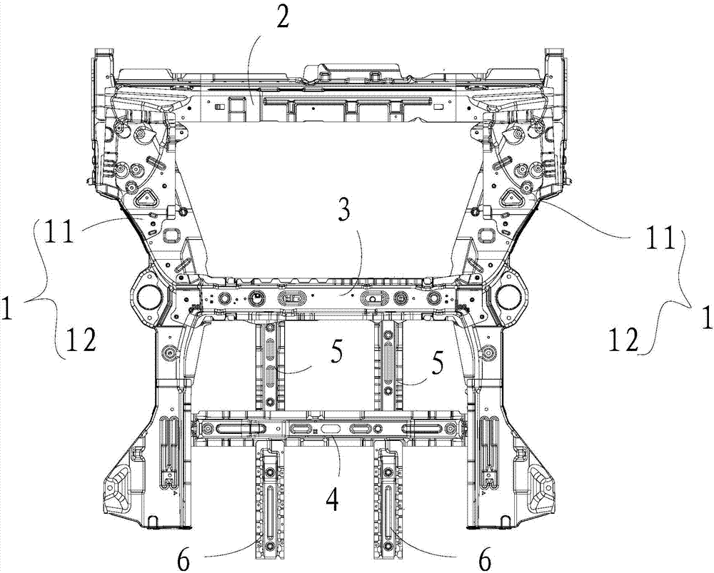
[0029] This embodiment relates to a vehicle rear floor frame structure, which is suitable for a vehicle with a short rear overhang, so as to improve the overall mode of the vehicle rear floor and ensure the reliability of the structure at the rear floor. Such as figure 1 As shown in , the rear floor frame structure of the vehicle includes a pair of longitudinal beams 1 extending along the length direction of the vehicle, and a beam assembly extending along the width direction of the vehicle is connected between the longitudinal beams 1 on both sides. The beam assembly specifically includes between the longitudinal beams 1 connected on both sides, and is close to the rear of the vehicle, that is, with figure 1 The direction shown in is the reference, the first beam 2 connected between the tops of the longitudinal beams 1 on both sides.

[0030] In this embodiment, the crossbeam assembly further includes a second crossbeam 3 connected between the longitudinal beams 1 on both si...

Embodiment 2

[0039] This embodiment relates to a vehicle body on which the vehicle rear floor frame structure as described in Embodiment 1 is installed. Meanwhile, the present embodiment also relates to a vehicle having the vehicle body as described above. The vehicle body and vehicle of this embodiment can ensure the structural strength of the rear floor of the vehicle by adopting the vehicle rear floor frame structure as described in Embodiment 1, and can ensure the reliability of force transmission at the rear floor of the vehicle when the vehicle collides, thereby improving The overall mode at the rear floor of the vehicle.


PUM


Abstract

The invention provides a vehicle rear-floor frame structure, a vehicle body and a vehicle. The vehicle rear-floor frame structure comprises a pair of longitudinal beams and a cross beam assembly, wherein the cross beam assembly enables the longitudinal beams to be connected with each other. The cross beam assembly comprises a first cross beam, a second cross beam, a third cross beam, a first longitudinal beam set and a second longitudinal beam set, wherein the first cross beam, the second cross beam and the third cross beam are arranged at intervals, the first longitudinal beam set connects the second cross beam with the third cross beam, and the second longitudinal beam set extends towards a vehicle head from the third cross beam. The first longitudinal beam set comprises two first branched longitudinal beams arranged in a spaced mode, the second longitudinal beam set comprises two second branched longitudinal beams arranged in a spaced mode, and the second branched longitudinal beams and the first branched longitudinal beams are arranged in a one-to-one correspondence mode so as to be located on the same straight lines. The vehicle rear-floor frame structures are installed on the vehicle body and the vehicle. According to the vehicle rear-floor frame structure, the structural strength and the reliability of the frame structure at a rear floor can be guaranteed, the rigidity and the bending resistance of the cross beams can be improved, the constancy of a vehicle body force transferring channel can also be guaranteed, and the integral mode of the vehicle rear floor can be improved.

Description

technical field [0001] The invention relates to the technical field of vehicles, in particular to a vehicle rear floor frame structure suitable for vehicles with short rear overhangs. The present invention also relates to a vehicle body equipped with the rear floor frame structure of the vehicle, and a vehicle with the vehicle body. Background technique [0002] The vehicle rear floor frame structure is an important part of the vehicle body structure, which is mainly used for supporting the rear floor and for the installation arrangement of related structural parts. The rear floor beam frame structure of existing vehicles is mostly composed of cross beams and longitudinal beams. In actual use, it is found that there are problems such as insufficient force transmission of the longitudinal beams, insufficient overall rigidity, and weak beam structures that are prone to bending. It will affect the overall mode of the rear floor, and there are also hidden dangers such as the fa...

Claims


Application Information

Patent Timeline
IPC IPC(8): B62D25/20
CPCB62D25/20
Inventor 檀庆榜朱春明刘磊谭欢沈会
Owner GREAT WALL MOTOR CO LTD
Why Eureka
Try Eureka