
A kind of automobile air conditioning assembly

An automotive air conditioner and assembly technology, which is applied to vehicle parts, air handling equipment, heating/cooling equipment, etc., can solve the problem of not meeting the comfort requirements of passengers, the use effect of air conditioners not meeting the requirements, and the internal sealing of air conditioners To improve the resistance to high and low temperature shocks, improve refrigeration efficiency, and avoid external air leakage

Active Publication Date: 2019-09-24
DONGFENG BEHR THERMAL SYST
View PDF5 Cites 0 Cited by
  • Summary
  • Abstract
  • Description
  • Claims
  • Application Information

AI Technical Summary

Problems solved by technology

The existing automobile air conditioner consists of a blower assembly and an air distributor assembly. Due to structural design defects in the traditional automobile air conditioner, the internal sealing of the air conditioner is not good, so that the use effect of the air conditioner cannot meet the requirements; Due to the limitation of the wind plate structure, the air blown out of the air outlet of the air conditioner is not uniform enough to meet the comfort requirements of passengers; because the sensor head of the temperature sensor in the car is far away from the negative pressure area at the front end of the blower, it takes a long time to The air induction pipe or corrugated pipe guides the old internal air in the negative pressure area to the sensing head. This method has great limitations and requires a lot of space

Method used


Image

  • A kind of automobile air conditioning assembly
  • A kind of automobile air conditioning assembly
  • A kind of automobile air conditioning assembly

Examples


Embodiment Construction

[0030] The present invention will be further described below in conjunction with the accompanying drawings and specific embodiments.

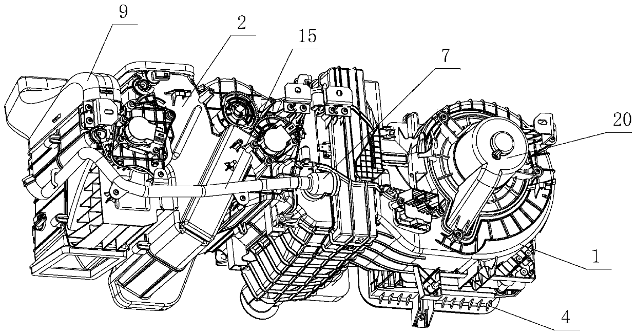
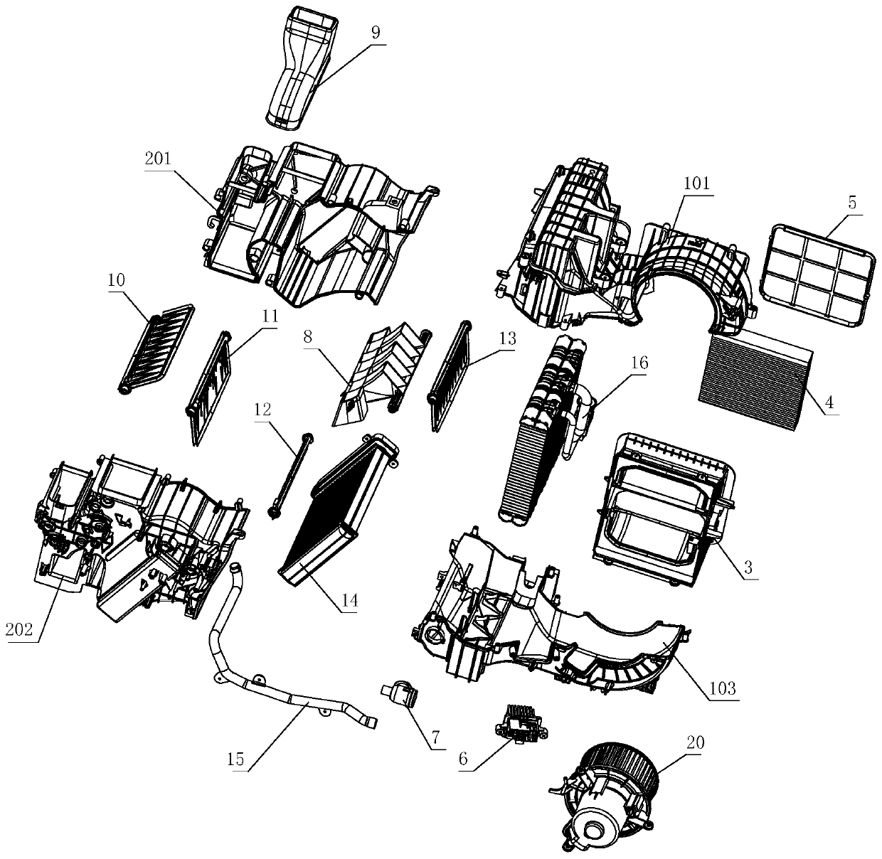
[0031] Such as Figure 1-2 Shown, a kind of automobile air-conditioning assembly of the present invention comprises blower assembly and component air device assembly, blower assembly and component air device assembly are fixedly connected by evaporator housing 1 and air distributor housing 2 (as figure 1 The evaporator shell 1 is composed of two half shells, that is, the evaporator upper shell 101 and the evaporator lower shell 102 are fixed together by screws to form the evaporator shell 1, The blower assembly includes a blower 20, an evaporator 16, an air intake assembly 3, a filter 4 and an air intake grid 5, the blower 20 is fixedly installed in the rear side of the evaporator shell 1, and the evaporator 16 is installed in the evaporator shell 1 Behind the blower 20 air passage, it is used to cool the air drawn in by the blower 20. The air...


PUM


Abstract

The invention relates to an automobile air conditioner technology, in particular to an automobile air conditioner assembly. The Automobile air conditioner assembly comprises an air blower assembly and an air distributing device assembly. An air door is matched with an air distributing device shell through bearing bush rubber edges to avoid air leakage of the two ends of the air door and improve the air tightness of the air door; through interference fit design of a boss and a groove which are designed on / in the matching surface of the shell, external air leakage is avoided, and the air tightness of an overall structure is further improved; the technical scheme for improving the reliability of an air conditioner is divided into improvement of the shock-resisting property and improvement of the high-and-low-temperature-resisting property; a specific air blocking mechanism is arranged at the bottom of an evaporator to ensure that air entering through an air inlet grid can pass through the evaporator, and refrigerating efficiency of the evaporator is improved, and the situation that condensate water does not splash in the discharging process is guaranteed; and a hot air channel and a cold air channel are each formed into a cylinder shape with the two open ends, cold air coming out of the evaporator is guided to a hot air area, and hot air coming out of an air heating core is guided to a cold air area, so that the cold air and the hot air are effectively mixed in a mixing area.

Description

technical field [0001] The invention relates to an automobile air-conditioning technology, in particular to an automobile air-conditioning assembly. Background technique [0002] The automotive air conditioning system is a device that cools, heats, ventilates and purifies the air in the cabin. It can provide a comfortable riding environment for the passengers, reduce the driver's fatigue intensity and improve driving safety. The existing automobile air conditioner consists of a blower assembly and an air distributor assembly. Due to structural design defects in the traditional automobile air conditioner, the internal sealing of the air conditioner is not good, so that the use effect of the air conditioner cannot meet the requirements; Due to the limitation of the wind plate structure, the air blown out of the air outlet of the air conditioner is not uniform enough to meet the comfort requirements of passengers; since the sensor head of the temperature sensor in the car is f...

Claims


Application Information

Patent Timeline
Patent Type & Authority Patents(China)
IPC IPC(8): B60H1/00B60H1/34
Inventor 张永波雷书翠洪进权妮
Owner DONGFENG BEHR THERMAL SYST
Learn More