
Voltage flicker suppression method and device

A voltage flicker and compensation device technology, applied in circuit devices, AC network voltage adjustment, AC network circuits, etc., can solve the problems of easy generation of harmonics, insufficient response speed of capacitor banks and SVCs, waste of resources, etc. Effects of voltage flicker, fast and smooth reactive power and active power, and stable output power

Inactive Publication Date: 2017-11-03
STATE GRID CORP OF CHINA +2
View PDF1 Cites 6 Cited by
  • Summary
  • Abstract
  • Description
  • Claims
  • Application Information

AI Technical Summary

Problems solved by technology

[0004] The disadvantage of the existing technology is that the response speed of the parallel capacitor bank and SVC is not fast enough, and harmonics are easily generated during the compensation process, and the best compensation state cannot be achieved, and the ability to suppress voltage flicker is limited
In addition, the method of directly installing the compensation device at the outlet of the photovoltaic or wind turbine has the problem of low utilization rate, and the probability of the compensation device being shut down will increase, resulting in waste of resources and high system operating costs
[0005] In addition, the existing new energy grid-connected systems seldom take advantage of the optimal combination of wind, solar and storage capacity to suppress voltage flicker, often resulting in the phenomenon of abandoning wind and solar, and the reliability of load power consumption cannot be guaranteed.

Method used


Image

  • Voltage flicker suppression method and device
  • Voltage flicker suppression method and device
  • Voltage flicker suppression method and device

Examples


no. 1 example

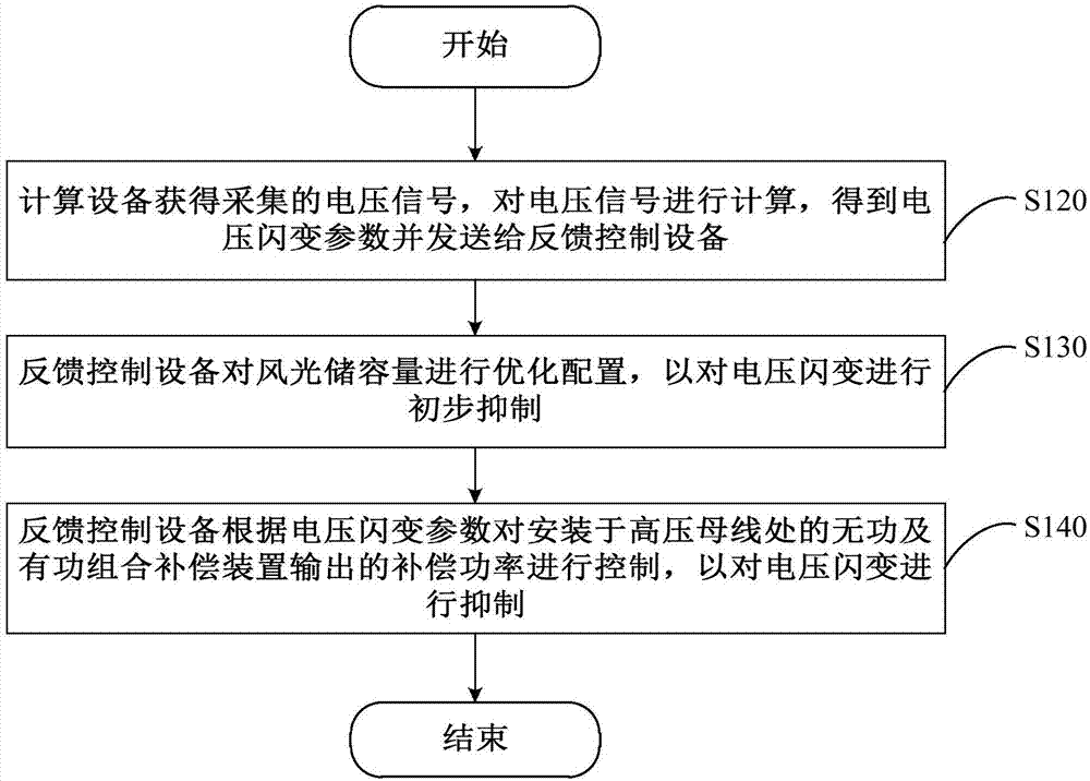
[0045] Please refer to image 3 , image 3 It is one of the flow charts of the steps of the voltage flicker suppression method provided in the first embodiment of the present invention. The method is applied to a new energy grid-connected system, and the new energy grid-connected system includes a computing device 300 and a feedback control device 100 connected to each other. The specific flow of the voltage flicker suppression method will be described in detail below.

[0046] Step S120 , the calculation device 300 obtains the collected voltage signal, calculates the voltage signal, obtains a voltage flicker parameter, and sends it to the feedback control device 100 .

[0047] Please refer to Figure 4 , Figure 4 provided by the first embodiment of the present invention image 3 The sub-step flowchart of step S120 is shown. The step S120 includes sub-step S121, sub-step S122, sub-step S123 and sub-step S124.

[0048] In sub-step S121 , the computing device 300 receive...

no. 2 example

[0088] Please refer to Figure 7 , Figure 7 It is a flowchart of the steps of the method for suppressing voltage flicker provided by the second embodiment of the present invention. The method is applied to the feedback control device 100 connected with the computing device 300, and the method includes:

[0089] Step S210, acquiring a voltage flicker parameter obtained by calculating the voltage signal by the computing device 300.

[0090] In this embodiment, for the description of the voltage flicker parameter obtained by calculating the voltage signal by the computing device 300, reference may be made to the above description of step S120.

[0091] Step S220, optimize the allocation of wind and solar storage capacity, so as to preliminarily suppress voltage flicker.

[0092] In this embodiment, the wind-solar storage capacity is the capacity of wind turbines, photovoltaic power plants and energy storage units. For a specific description of step S220, reference may be mad...

no. 3 example

[0096] Please refer to Figure 8 , Figure 8 A functional block diagram of the voltage flicker suppression device 200 provided in the third embodiment of the present invention. The voltage flicker suppression device 200 is applied to the feedback control device 100 connected to the computing device 300 . The device includes: an acquisition module 210 , an optimization module 220 and a control module 230 .

[0097] The acquiring module 210 is configured to acquire the voltage flicker parameter calculated by the computing device 300 on the voltage signal.

[0098] In this embodiment, the acquisition module 210 is used to execute Figure 7 In step S210, for a specific description of the acquisition module 210, please refer to Figure 7 In step S210 and image 3 The description of step S120 in.

[0099] The optimization module 220 is used to optimize the allocation of wind-solar storage capacity to preliminarily suppress voltage flicker, wherein the wind-solar storage capaci...


PUM


Abstract

The invention provides a voltage flicker suppression method and device. The method is applied to a new energy grid-connected system comprising calculation equipment and feedback control equipment, wherein the calculation equipment is used for obtaining an acquired voltage signal, calculating the voltage signal to obtain a voltage flicker parameter and sending the voltage flicker parameter to the feedback control equipment, the feedback control equipment is used for performing configuration optimization on wind-light storage capacity so as to initially control a voltage flicker, and the feedback control equipment is used for controlling a compensated power output from a reactive power and active power combined compensation device arranged at a high-voltage bus according to the voltage flicker parameter so as to suppress the voltage flicker. Therefore, the reactive power and the active power which are required by a system can be rapidly and smoothly compensated, the output power of new energy is stabilized, the voltage flicker is effectively suppressed, and moreover, the voltage flicker is initially suppressed by means of the advantage of wind-light storage capacity optimized combination.

Description

technical field [0001] The present invention relates to the technical field of voltage flicker suppression, in particular to a voltage flicker suppression method and device. Background technique [0002] Human beings are worried about energy security and environmental degradation, making the full use of renewable energy a global consensus. New energy grid-connected power generation represented by solar energy and wind energy has become an irresistible development trend of new power systems. The output power of renewable energy such as solar energy and wind energy has strong volatility, which is likely to cause voltage fluctuation and flicker at the public connection point of the power grid, and the voltage flicker phenomenon will cause harm to people's life and work. With the increase of grid-connected installed capacity of photovoltaic and wind farms, research on voltage flicker suppression strategies is of great significance. [0003] At this stage, the idea of ​​suppres...

Claims


Application Information

Patent Timeline
Patent Type & Authority Applications(China)
IPC IPC(8): H02J3/38H02J3/16
CPCH02J3/16H02J3/38H02J2203/20Y02E40/30
Inventor 颛孙旭朱岸明孙自安李复明许斐赵胜利王麦锋王育路刘毅刘宏伟冯文刚
Owner STATE GRID CORP OF CHINA
Learn More