
Induction cooker

An induction cooker and electromagnetic coil technology, applied in the field of induction cookers, can solve problems such as poor heat dissipation effect, high temperature ignition of the induction cooker coil plate, and failure of the induction cooker to work normally, so as to achieve the effects of accelerating heat discharge, saving energy and increasing specific surface area.

Inactive Publication Date: 2017-11-03
弘毅天承知识产权股份有限公司
View PDF0 Cites 0 Cited by
  • Summary
  • Abstract
  • Description
  • Claims
  • Application Information

AI Technical Summary

Problems solved by technology

[0004] The object of the present invention is to provide an induction cooker with better heat dissipation effect in view of the phenomenon that the above-mentioned electromagnetic cooker has a poor heat dissipation effect when it works at high power for a long time, which leads to the problem that the induction cooker cannot work normally, and even the coil disk of the induction cooker catches fire at high temperature.

Method used


Image

  • Induction cooker
  • Induction cooker

Examples


Embodiment 1

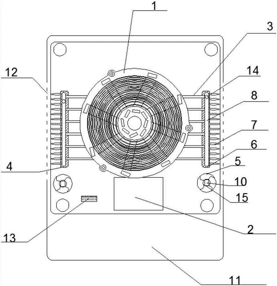
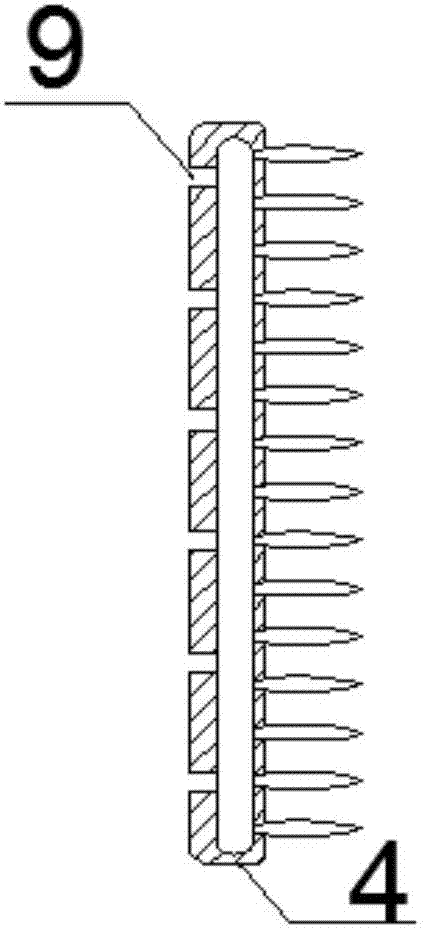
[0026] An induction cooker includes an electromagnetic coil pan assembly 1 and an induction cooker main control board assembly 2 arranged on one side of the electromagnetic coil pan assembly 1, and also includes a plurality of heat pipes 3, a heat dissipation assembly 4 and a heat dissipation fan 5, and the heat dissipation assembly 4 Symmetrically arranged on both sides of the electromagnetic coil disk assembly 1, the heat dissipation assembly 4 includes a heat dissipation base 6 and heat dissipation fins 7, a cavity 8 is provided inside the heat dissipation base 6, and heat dissipation fins are provided on the wall of the heat dissipation base 6 7. One end of the heat dissipation fin 7 communicates with the cavity 8, and the heat dissipation base 6 is provided with a plurality of grooves 9 at the position corresponding to the heat dissipation fin 7, and the heat pipe 3 is fixed in the groove 9, and the heat pipe 3 The other end is fixedly connected to the electromagnetic coil...

Embodiment 2

[0028] On the basis of Embodiment 1, it also includes an induction cooker bottom case 11, the induction cooker bottom case 11 is fixedly connected to the electromagnetic coil disk assembly 1, and the induction cooker bottom case 11 is provided with heat dissipation holes at positions corresponding to the heat dissipation fins 7 12. In this embodiment, the heat on the heat dissipation assembly 4 can be quickly transferred out through the heat dissipation holes 12 .

Embodiment 3

[0030] On the basis of Embodiment 1 or 2, an automatic controller 13 is arranged on the bottom shell 11 of the induction cooker; further, a temperature sensor 14 is arranged in the cavity 8 of the base; further, the heat dissipation The fan 5 is driven by a motor 10, and a speed reducer 15 is arranged on the cooling fan. In this embodiment, the rotating speed of the heat dissipation fan 5 can be automatically adjusted according to the temperature of the heat dissipation assembly 4, which not only accelerates the dissipation of heat, but also saves energy.


PUM


Abstract

The invention discloses an induction cooker. The induction cooker comprises an electromagnetic coil disc assembly and an induction cooker main control panel assembly arranged on one side of the electromagnetic coil disc assembly, and further comprises multiple heat pipes, heat radiation assemblies and heat radiation fans. The heat radiation assemblies are symmetrically arranged on the two sides of the electromagnetic coil disc assembly. Each heat radiation assembly comprises a heat radiation base body and heat radiation wings. A cavity is formed in each heat radiation base body. One end of each heat radiation wing communicates with the corresponding cavity. Multiple grooves are formed in the positions, opposite to the corresponding heat radiation wings, of each heat radiation base body. The heat pipes are fixed in the grooves. The other end of each heat pipe is fixedly connected to the electromagnetic coil disc assembly. Each heat radiation fan is arranged on one side of the corresponding heat radiation assembly. By means of the multiple heat pipes, heat is fast conducted into the heat radiation base bodies of the heat radiation assemblies; and due to the fact that each heat radiation base body is provided with the cavity, the specific surface area of the heat radiation assemblies is increased, and heat is fast discharged through the heat radiation assemblies under the action of the heat radiation fans.

Description

technical field [0001] The invention relates to the field of household appliances, in particular to an electromagnetic cooker. Background technique [0002] Induction cooker is a commonly used kitchen appliance. Its principle is the phenomenon of electromagnetic induction: using alternating current to generate an alternating magnetic field whose direction is constantly changing through the coil, eddy current will appear inside the conductor in the alternating magnetic field, which is eddy current. The electric field promotes the movement of carriers in the conductor; the Joule heating effect of the eddy current makes the conductor warm up, thereby realizing heating. [0003] In the existing heat dissipation device of the induction cooker, the coil plate of the induction cooker or the main control board is directly connected to the heat sink for heat dissipation, and the assembly position of the heat sink is limited by the assembly position of the power tube and the rectifier...

Claims


Application Information

Patent Timeline
Patent Type & Authority Applications(China)
IPC IPC(8): F24C7/06H05B6/12H05B6/42
CPCF24C7/067H05B6/1263H05B6/42H05B2206/02
Inventor 樊明伟
Owner 弘毅天承知识产权股份有限公司
Learn More