Material rack for building construction
A technology for building construction and material racks, applied in the directions of containers, packaging, transportation and packaging, it can solve the problems of material rack dumping, inconvenient material loading and unloading, etc., and achieve the effects of convenient material loading and unloading, stable structure and high safety.
- Summary
- Abstract
- Description
- Claims
- Application Information
AI Technical Summary
Problems solved by technology
Method used
Image
Examples
specific Embodiment approach 1
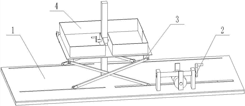
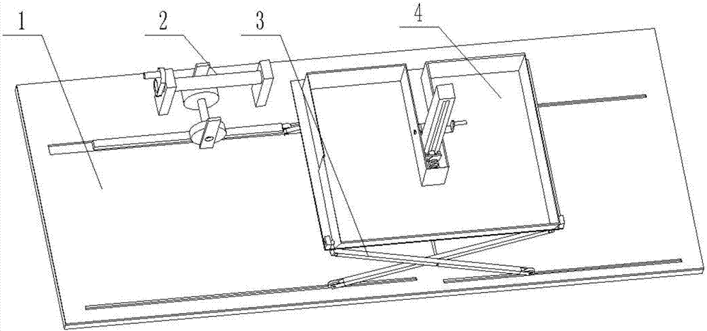
[0039] Combine below figure 1 , 2 , 3, 4, 5, 6, 7, 8, 9, 10, 11, 12, 13, 14 illustrate this embodiment, a material rack for building construction, including a bottom plate 1, a height adjustment mechanism 2, a lifting frame 3, The material box 4 is characterized in that: the right front end of the upper end surface of the base plate 1 is provided with a height adjustment mechanism 2, the upper end of the base plate 1 and the left end of the height adjustment mechanism 2 are provided with a lifting frame 3, and the upper end of the lifting frame 3 is provided with a material box 4;
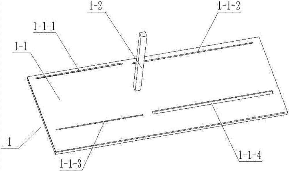
[0040] The base plate 1 includes a rectangular base plate 1-1, a rectangular column 1-2, a first rectangular chute 1-1-1 is provided at the left rear end of the upper end surface of the rectangular base plate 1-1, and a right rear end of the upper end surface of the rectangular base plate 1-1 Set the second rectangular chute 1-1-2, set the third rectangular chute 1-1-3 at the left front end of the...
specific Embodiment approach 2
[0044] Combine below figure 1 , 2 . One connecting rod bushing 3-10-1, hinge shaft 3-10-2, second connecting rod bushing 3-10-3, first connecting rod bushing 3-10-1, second connecting rod bushing 3 -10-3 are all rectangular tubular structures hollowed out inside. The rear end of the first connecting rod sleeve 3-10-1 and the front end of the second connecting rod sleeve 3-10-3 are each provided with a circular bearing seat by welding The bearing seat of the hole, the rear end of the first connecting rod sleeve 3-10-1 is connected to the hinged shaft 3-10-2 through a bearing, and the rear end of the hinged shaft 3-10-2 is connected to the second connecting rod sleeve 3-10 through a bearing -3, the hinged shaft 3-10-2 has an interference fit with the inner ring of the bearing, and the bearing seat with a circular bearing seat hole forms an interference fit with the outer ring of the bearing, and the connecting rod connecting device 3-10 is provided with two , the first connec...
specific Embodiment approach 3
[0045] Combine below figure 1 , 2 . -3-1, rotating shaft 4-3-2, gear I 4-3-3, dumping rocker arm 4-3-4, dumping rocking bar 4-3-5, pin 4-3-6, rotating shaft 4-3-2 The right end is connected to the gear I 4-3-3 through a key, the left end of the rotating shaft 4-3-2 is welded and connected to the tilting rocker arm 4-3-4, and the upper end of the left end surface of the tilting rocker arm 4-3-4 is connected to the tilting rocker 4-3 through a bearing -5, a sleeve 4-3-1 is arranged between the outer end of the rotating shaft 4-3-2, the tilting rocker arm 4-3-4 and the gear I 4-3-3, and the right end of the sleeve 4-3-1 is welded Connected to the left end outer wall of the rectangular notch 4-2, the rotating shaft 4-3-2 passes through the left end wall of the rectangular notch 4-2 to form a clearance fit, and the right end of the rotating shaft 4-3-2 passes through the bearing and the rectangular notch 4-2 The right end wall is connected; the rear end of the gear I 4-3-3 is me...
PUM
 Abstract
Description
Claims
Application Information
 - R&D Engineer
- R&D Manager
- IP Professional
- Industry Leading Data Capabilities
- Powerful AI technology
- Patent DNA Extraction
Browse by: Latest US Patents, China's latest patents, Technical Efficacy Thesaurus, Application Domain, Technology Topic, Popular Technical Reports.
© 2024 PatSnap. All rights reserved.Legal|Privacy policy|Modern Slavery Act Transparency Statement|Sitemap|About US| Contact US: help@patsnap.com


