
Automatic connected pad printing machine

A pad printing machine, automatic technology, applied in printing machines, rotary printing machines, printing, etc., can solve the problems of wasting manpower and material resources

Pending Publication Date: 2017-11-03
东莞市中民自动化有限公司
View PDF9 Cites 4 Cited by
  • Summary
  • Abstract
  • Description
  • Claims
  • Application Information

AI Technical Summary

Problems solved by technology

[0004] In view of this, the present invention aims at the deficiencies of the existing technology, and its main purpose is to provide an automatic one-piece pad printing machine, which realizes full automation such as automatic dismantling of finished products, automatic delivery of jigs, automatic loading of workpieces, and automatic pad printing. The manufacturing process improves the working efficiency of the pad printing machine, solves the problem of wasting manpower and material resources, and reduces the production cost. At the same time, the overall manufacturing process is stable, good controllability, safe and reliable, and the processing precision is high, which improves the processing quality.

Method used


Image

  • Automatic connected pad printing machine
  • Automatic connected pad printing machine
  • Automatic connected pad printing machine

Examples


Embodiment Construction

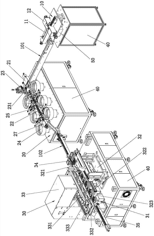
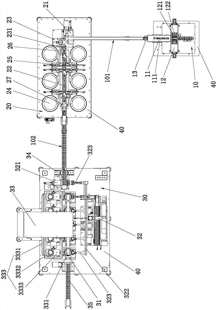
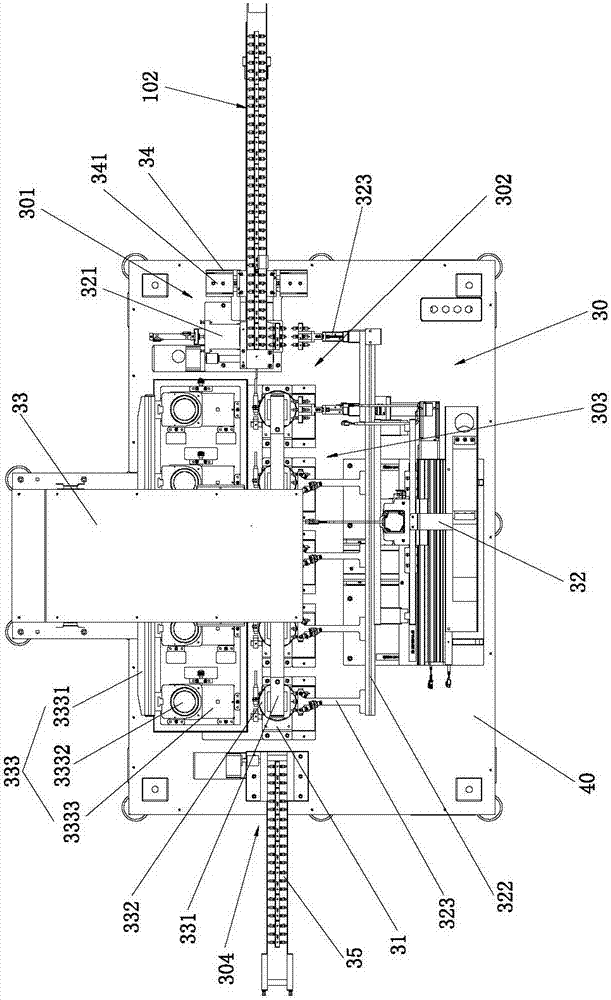
[0061] Please refer to Figure 1-Figure 8 Shown, it has shown the concrete structure of two kinds of embodiments of the present invention, wherein, Figure 1-7 Shown mainly shows the concrete structure of embodiment one, Figure 8 The shown mainly shows the partial structure of Embodiment 2; it includes an automatic conveying jig unit 10, an automatic workpiece loading unit 20, and an automatic pad printing unit 30 connected sequentially in sequence; the automatic pad printing unit 30 includes sequentially connected input Material area 301 , pad printing area 303 and finished product output area 304 .

[0062] Specifically, the pad printing area 303 has a plurality of jig placement rotary platforms 31 arranged side by side at intervals, and a jig transfer device 32, The pad printing device 33 ; the jig transfer device 32 is connected between the feeding area 301 , the rotating platform 31 for placing each jig and the finished product output area 304 .

[0063] Between the f...


PUM


Abstract

The invention discloses an automatic connected pad printing machine which comprises an automatic jig conveying unit, an automatic workpiece loading unit and an automatic pad printing unit which are sequentially connected according to the manufacture procedure sequence. The automatic pad printing unit comprises a feeding area, a pad printing area and a finished product output area. The pad printing area is provided with a plurality of jig storing rotary carrying tables, and jig transferring devices and pad printing devices are arranged on the two sides of the jig storing rotary carrying tables correspondingly. Each jig transferring device comprises a first pushing device body, a first displacement support, a first horizontal driving device body, a first lifting driving device body and a plurality of displacement manipulators. Each pad printing device is provided with a second displacement support, a plurality of pad printing heads, a plurality of ink disc assemblies, a second horizontal driving device body and a second lifting driving device body. Thus, through the automatic jig conveying unit, the automatic workpiece loading unit and the second lifting driving device bodies which are sequentially connected according to the manufacture procedure sequence, full-automatic manufacture procedures such as finished product automatic disassembly, jig automatic transferring, workpiece automatic loading and automatic pad printing are achieved, the working efficiency of the pad printing machine is improved, and the cost is reduced.

Description

technical field [0001] The invention relates to the technology in the field of pad printing equipment, in particular to an automatic connected pad printing machine. Background technique [0002] Pad printing is an indirect intaglio printing technology, which has become the main method for surface printing and decoration of various objects. However, the pad printing equipment in the prior art is usually an independent production equipment, which only performs pad printing on the jig with the workpiece installed, and cannot realize the full automation of feeding the jig, loading the workpiece, pad printing and dismantling the finished product. During the production process, the carrier needs to be replaced many times, which affects the working efficiency of the pad printing machine, wastes manpower and material resources, and increases the cost of production; secondly, due to the influence of the driving mode in the process, the overall process lacks reliability. Controllabil...

Claims


Application Information

Patent Timeline
IPC IPC(8): B41F17/00B65G47/91B65G47/82B65G37/00
CPCB65G37/00B65G47/82B65G47/91B41F17/001
Inventor 钟健良
Owner 东莞市中民自动化有限公司
Learn More