


Quick Research
Generate reliable direction feasibility study reports for your R&D in just a few steps.

Technical Q&A
Discover and master advanced knowledge NOW. Basics, ideas, possibilities, all at once.

Find Solutions
As an expert in R&D theories, this can generate solutions to your technical problems instantly.

Evaluate Feasibility
Analyze your overall solution with one click, know your potential R&D risks in advance.

Monitor Landscape
Get weekly tech updates, stay abreast of the latest tech innovations and key insights.
Glue dispensing equipment and glue dispensing method thereof
A technology of dispensing and equipment, applied in the direction of coating, device for coating liquid on the surface, etc., can solve the problems of complex operation, affecting production efficiency, difficult to control the amount of dispensing, etc., to improve the utilization rate and accurately control the glue output. amount of effect
- Summary
- Abstract
- Description
- Claims
- Application Information
AI Technical Summary
Problems solved by technology
Method used
Image

Examples
Embodiment 1
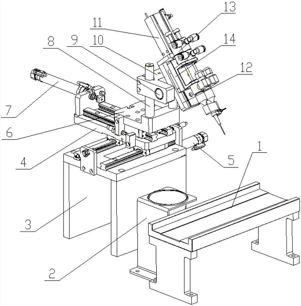
[0024] Such as figure 1 and figure 2 As shown, a dispensing equipment and dispensing method thereof include a base 3, a lateral moving plate 4, a horizontal cylinder 5, a longitudinal moving plate 6, a longitudinal cylinder 7, an adjustment column 8, an angle adjustment column 9, and an adjustment block 10 , lifting cylinder 11, angle block 12, dispensing device 13, lifting block 14 and slide rail, described lateral movement plate 4 is connected on the base 3 by slide rail, and described horizontal cylinder 5 is arranged on the base 3, so The power rod of the horizontal cylinder 5 is connected with the laterally moving plate 4, and the longitudinally moving plate 6 is connected on the laterally moving plate 4 through slide rails. Connected with the longitudinal moving plate 6, the adjusting column 8 is arranged on the longitudinal moving plate 6, the adjusting block 10 is fixed on the adjusting column 8 by bolts, and the two ends of the angle adjusting column 9 are fixed on ...
Embodiment 2
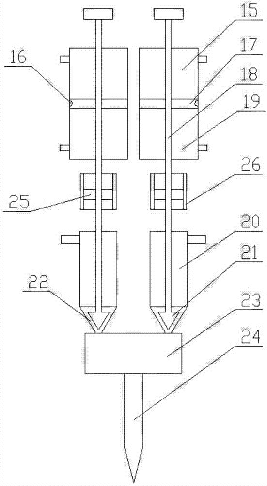
[0030] On the basis of Embodiment 1, the sealing sheet 17 is controlled to move up and down in the sealing tank 19 through the air inlet and the air outlet, the sealing sheet 17 drives the sealing rod 18 to move up and down, and the sealing rod 18 drives the tapered sealing head 21 to move up and down, To control the tapered sealing head 21 to block the glue outlet 22, when the glue inlet injects glue into the glue tank 20, the distance between the tapered sealing head 21 and the glue outlet 22 is controlled by the sealing rod 18, so that The glue output of each quantitative glue injection device 15 is controlled; the airflow velocity of the air inlet and air outlet on the sealed tank 19 is controlled by the cylinder regulating valve, so that each quantitative glue injection device 15 can output glue when various glues are mixed. The ratio is effectively controlled; the quality of the glue after mixing is effectively improved; by designing the glue outlet 22 into a tapered glue...
Embodiment 3
[0032] On the basis of embodiment 2, by being provided with scale marks on the adjustment column 8, the adjustment block 10 is accurately adjusted in height; the angle dial is set on the angle adjustment column 9, so that the angle adjustment between the angle block 12 and the horizontal plane is more accurate. Accurate, record the height of the adjustment block 10 and the angle of the angle block 12 to facilitate subsequent equipment debugging and adjustment, and through these numbers, the actual 3-latitude coordinates of the dispensing head 24 and the workpiece can be captured and input into the 3D file in the computer In order to obtain accurate coordinates for subsequent product dispensing products, it is convenient to directly adjust the height of the adjustment block 10 and the angle of the angle block 12 for subsequent product replacement; by setting the scale line on one end of the sealing rod 18, the sealing rod 18 can move up and down with a scale The speed at which t...
PUM
 Abstract
Description
Claims
Application Information
 - R&D Engineer
- R&D Manager
- IP Professional
- Industry Leading Data Capabilities
- Powerful AI technology
- Patent DNA Extraction
Browse by: Latest US Patents, China's latest patents, Technical Efficacy Thesaurus, Application Domain, Technology Topic, Popular Technical Reports.
© 2024 PatSnap. All rights reserved.Legal|Privacy policy|Modern Slavery Act Transparency Statement|Sitemap|About US| Contact US: help@patsnap.com