
Monocular computer vision technology-based target object distance measurement method and system

A technology of computer vision and target objects, applied in computer parts, calculations, instruments, etc., can solve the problems of random errors in distance measurement, complex installation procedures, large errors, etc., to reduce the probability of error introduction, reduce calculation variables, and measure The effect of numerical stabilization

Active Publication Date: 2017-10-31
WUHAN JIMU INTELLIGENT TECH CO LTD
View PDF8 Cites 18 Cited by
  • Summary
  • Abstract
  • Description
  • Claims
  • Application Information

AI Technical Summary

Problems solved by technology

[0003] For ranging components, the ranging method based on millimeter-wave radar will be affected by factors including the material, surface roughness, size and motion state of the detected object, and cannot judge the type of the detected object and predict its motion state
At the same time, the cost of millimeter-wave radar is relatively high, and the installation procedure is complicated
[0004] For the ranging algorithm, the sample size of the data regression model and the selection of the regression method directly affect the accuracy of ranging. Compared with stationary objects and the environment, the measurement of moving targets is more variable, so the data regression ranging The robustness of the model is relatively poor
In addition, the distance measurement accuracy based on the optical geometric model depends on the extraction accuracy of the image feature parameters. The jump of a few pixels of the feature parameters will cause a large error in long-distance measurement, and the change of ambient light will also affect the distance. The measurement introduces random errors, so its stability needs to be improved

Method used


Image

  • Monocular computer vision technology-based target object distance measurement method and system
  • Monocular computer vision technology-based target object distance measurement method and system
  • Monocular computer vision technology-based target object distance measurement method and system

Examples


Embodiment Construction

[0059] In order to make the object, technical solution and advantages of the present invention clearer, the present invention will be further described in detail below in conjunction with the examples. It should be understood that the specific embodiments described here are only used to explain the present invention, not to limit the present invention.

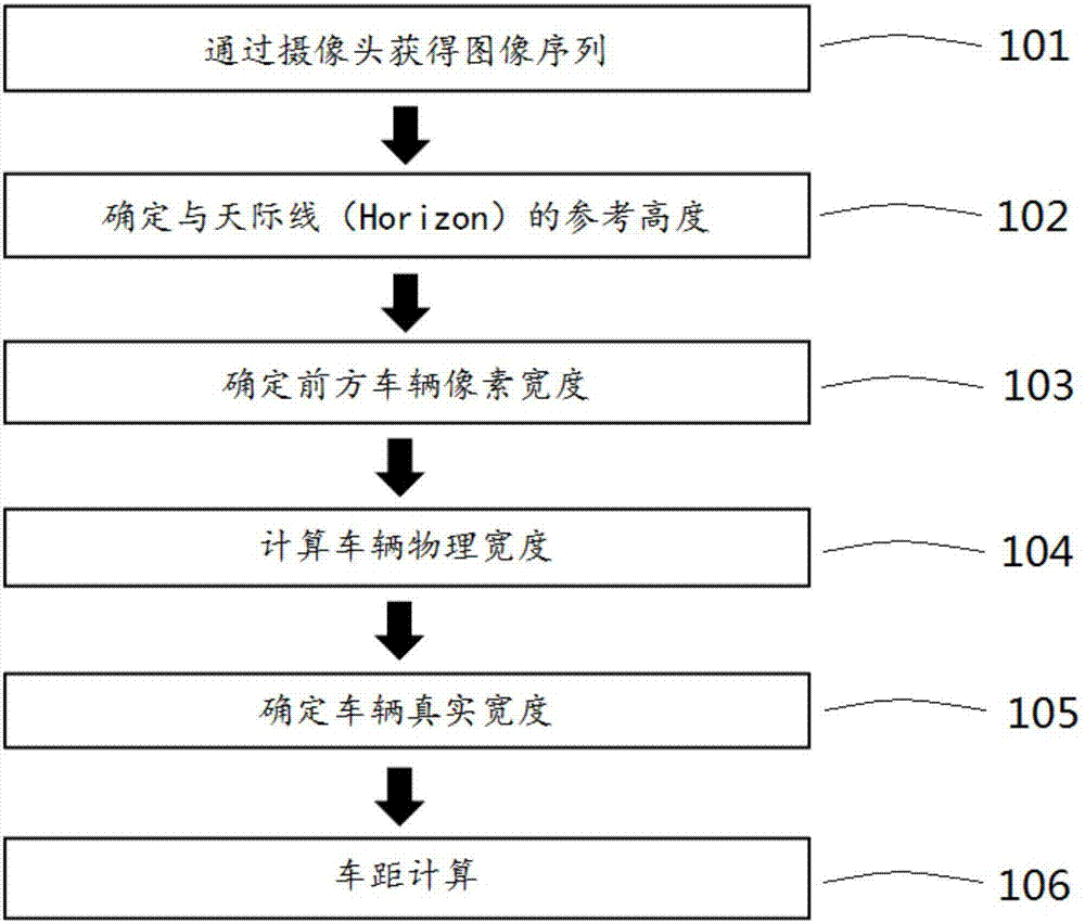
[0060] Such as figure 1 As shown, the target object distance measurement method based on monocular computer vision technology, the specific implementation steps of the distance measurement method are as follows:

[0061] Step 101: collecting sequence images through a single camera, and outputting the sequence images to be processed;

[0062] Step 102: Determine and optimize the value y of the skyline reference height. The main implementation schemes are:

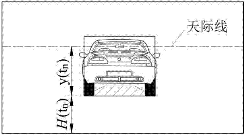
[0063] To calculate the reference height of the skyline, the edge of the target object must first be identified through target detection, such as figure 2 The bottom ed...


PUM


Abstract

The invention discloses a monocular computer vision technology-based target object distance measurement method and system. The method comprises the following steps of collecting a sequence image in front or back of a vehicle in real time through a camera; determining a reference height of a skyline according to the collected sequence image; taking a target with a constant physical size in the sequence image as a target object, and through a target detection method, determining a feature pixel size, used for distance measurement, of the target object; through an optical geometric model, determining the physical size of the target object; performing smoothing on a calculation result of the feature pixel size of the target object through a data smoothing method to output a stable physical size, and then calculating a real feature size of the target; and based on the calculated real feature size, performing calculation through the optical geometric model to obtain a distance of the target object. Multiple factors influencing distance measurement precision are considered more comprehensively, so that the calculation precision is improved.

Description

technical field [0001] The present invention relates to assisted driving technology, in particular to a method and system for measuring the distance of a target object based on monocular computer vision technology. Background technique [0002] In the field of automotive electronics, the distance monitoring warning function (Headway Monitoring Warning, HMW) and the collision warning function (Forward Collision Warning, FCW) of the advanced driving assistant system (Advanced Driving Assistant System, ADAS) must rely on distance measurement components and algorithms . Furthermore, if the adaptive cruise control (Adaptive Cruise Control, ACC) and automatic emergency braking (Autonomous Emergency Braking, AEB) functions are to be realized, the distance measurement must achieve a sufficiently high accuracy. At present, there are mainly two mainstream technologies for measuring the distance of obstacles ahead. The first is to collect images by monocular / binocular cameras, identif...

Claims


Application Information

Patent Timeline
IPC IPC(8): G06K9/00
CPCG06V20/588G06V20/56G06V20/58
Inventor 王述良许端刘国虎艾凯程建伟
Owner WUHAN JIMU INTELLIGENT TECH CO LTD
Learn More