Equipment for cooling monofilament tufts for annular extrusion

A technology of circular spinning and equipment, applied in the direction of filament/thread forming, textile and paper making, fiber processing, etc., to achieve the effect of high thermal conductivity

Active Publication Date: 2021-11-23
OERLIKON TEXTILE GMBH & CO KG
View PDF14 Cites 0 Cited by
  • Summary
  • Abstract
  • Description
  • Claims
  • Application Information

AI Technical Summary

Problems solved by technology

Here, however, the thermal boundary effect is increased due to the heated melt-carrying part inside the spin beam, so that the temperature difference in the supplied cooling air can still be greater.

Method used


Image

  • Equipment for cooling monofilament tufts for annular extrusion
  • Equipment for cooling monofilament tufts for annular extrusion
  • Equipment for cooling monofilament tufts for annular extrusion

Examples


Embodiment Construction

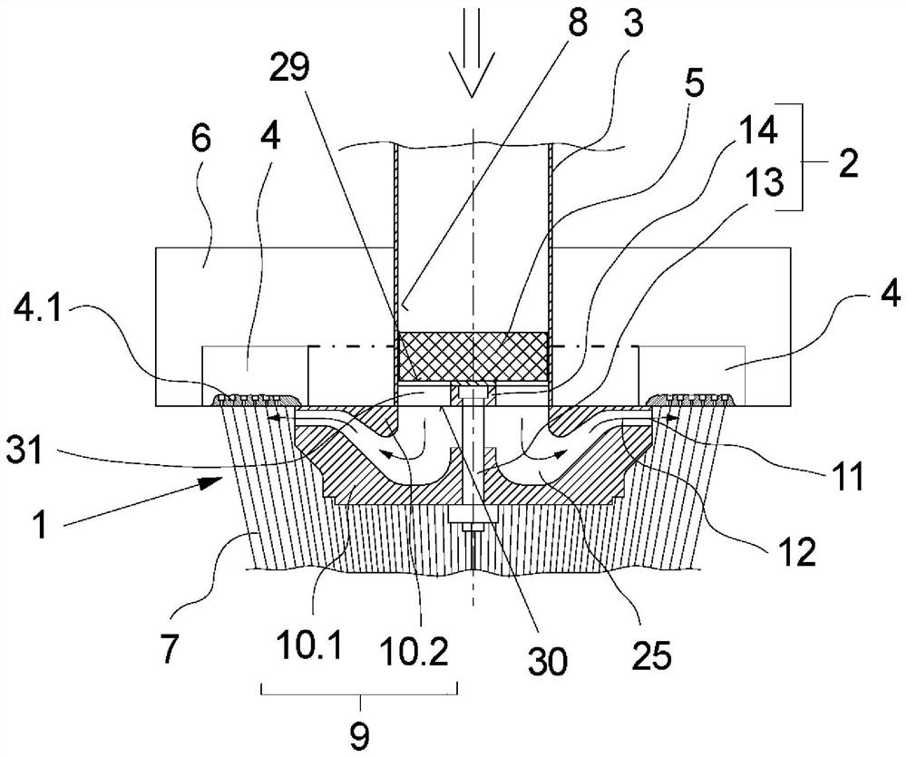
[0023] exist figure 1 A view of a first embodiment of a device according to the invention for cooling an annular extruded monofilament tuft is schematically shown in . The device is here integrated directly on the spin beam 6 . The spin beam 6 supports the annular spinning nozzle 4 on its underside. The annular spinning nozzle 4 has a plurality of nozzle openings 4 . 1 which are formed uniformly distributed on the underside of the annular spinning nozzle 4 . The annular spinning nozzle 4 is coupled to a spinning pump (not shown here) in order to extrude the polymer melt.

[0024] The connection adapter 2 is held centrally with respect to the annular spinning nozzle 4 on the underside of the spin beam 6 . The connection adapter 2 supports the blowing flow generator 1 which is arranged below the annular spinning nozzle 4 . The air blow generator 1 is formed in this exemplary embodiment by an air blow nozzle arrangement 9 . The air blow nozzle arrangement 9 has two nozzle pl...


PUM


Abstract

The invention relates to a device for cooling an annular extruded monofilament tuft extruded through a plurality of nozzle openings of an annular spinning nozzle. The device has a blow air generator which has a radially surrounding blow air outlet and is arranged centrally below the annular spinning nozzle. The blow flow generator is held by a connection adapter which connects the blow flow generator to the intake channel. In order to homogenize the incoming cooling air immediately before entering the blowing flow generator, in particular with respect to the temperature of the cooling air, according to the invention, the connection adapter is equipped with a porous metal foam, preferably porous aluminum foam - a flow barrier made of aluminum.

Description

technical field [0001] The invention relates to a device for cooling annular extruded monofilament tufts / curtains. Background technique [0002] During melt spinning / melt spinning synthetic fiber slivers or filaments, a plurality of fine sliver-shaped monofilaments are extruded through the nozzle holes of the spinning nozzles. For this purpose, the molten polymer is fed to the spinning nozzle under high pressure. To form a fiber sliver or a plurality of filaments, a plurality of sliver-shaped monofilaments are combined in their entirety or in bundles. Before merging, the monofilaments are cooled by a flow of cooling air so that the molten state of the monofilaments is converted to a solidified state after being discharged from the nozzle hole. Of particular importance for the quality of the fiber sliver or filament is the uniform cooling of all the individual filaments. It is therefore known in particular for the production of staple / staple fibers to guide a plurality of ...

Claims


Application Information

Patent Timeline
Patent Type & Authority Patents(China)
IPC IPC(8): D01D5/092
CPCD01D5/092D01D5/088
Inventor W-M·卡尔森-布拉克R·布莱斯莫尔
Owner OERLIKON TEXTILE GMBH & CO KG
Why Eureka
Try Eureka