An intelligent magnetic traction flue dust cleaning device and its control method

A flue dust removal and traction technology, which is applied in combustion methods, solid residue removal, lighting and heating equipment, etc., can solve the problems of unreasonable structure, high failure rate of equipment, high maintenance level, etc., and achieve simple operation and control , Adsorption and movement are sensitive, and the dust removal effect is good

Active Publication Date: 2019-03-29
HEFEI WISDOM DRAGON MACHINERY DESIGN CO LTD
View PDF4 Cites 0 Cited by
  • Summary
  • Abstract
  • Description
  • Claims
  • Application Information

AI Technical Summary

Problems solved by technology

However, due to the characteristics of the structure and medium, and the influence of the high temperature environment, the barrel of the soot blower is prone to jamming, failure, air leakage, etc., the equipment failure rate is relatively high, and a high level of maintenance is required. damage to the pipe wall
Due to the general effect of domestically produced soot blowers, the soot blowing effect is not obvious, and basically cannot remove the existing soot accumulation. Only when the soot blowing is used to prevent the occurrence of soot blowing opportunities, it must be manually cleaned once before soot blowing , otherwise the stubbornness cannot be removed. Therefore, it is a burden on manpower
The gas pulse shock wave soot blower can only be applied to the lower part of the tail flue with relatively low temperature due to the consideration of high-temperature flue gas and gas leakage after deflagration.
Secondly, there are certain potential safety hazards. Once the structure is unreasonable and the production quality is problematic, it is easy to cause the leakage of combustible gas and cause safety accidents.

Method used


Image

  • An intelligent magnetic traction flue dust cleaning device and its control method
  • An intelligent magnetic traction flue dust cleaning device and its control method
  • An intelligent magnetic traction flue dust cleaning device and its control method

Examples


Embodiment Construction

[0041]In order to make the purpose, technical solutions and advantages of the embodiments of the present invention clearer, the technical solutions in the embodiments of the present invention will be clearly and completely described below in conjunction with the accompanying drawings in the embodiments of the present invention. Obviously, the described embodiments It is some embodiments of the present invention, but not all of them. Based on the implementation manners in the present invention, all other implementation manners obtained by persons of ordinary skill in the art without creative efforts fall within the protection scope of the present invention. Accordingly, the following detailed description of the embodiments of the invention provided in the accompanying drawings is not intended to limit the scope of the claimed invention, but merely represents selected embodiments of the invention. Based on the implementation manners in the present invention, all other implementa...


PUM


Abstract

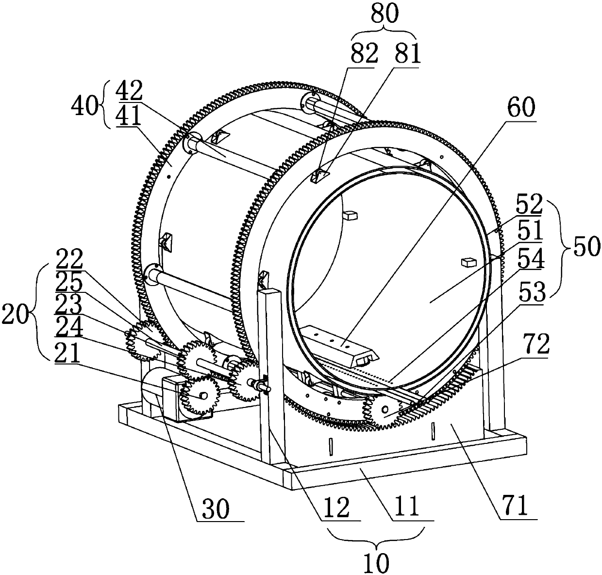
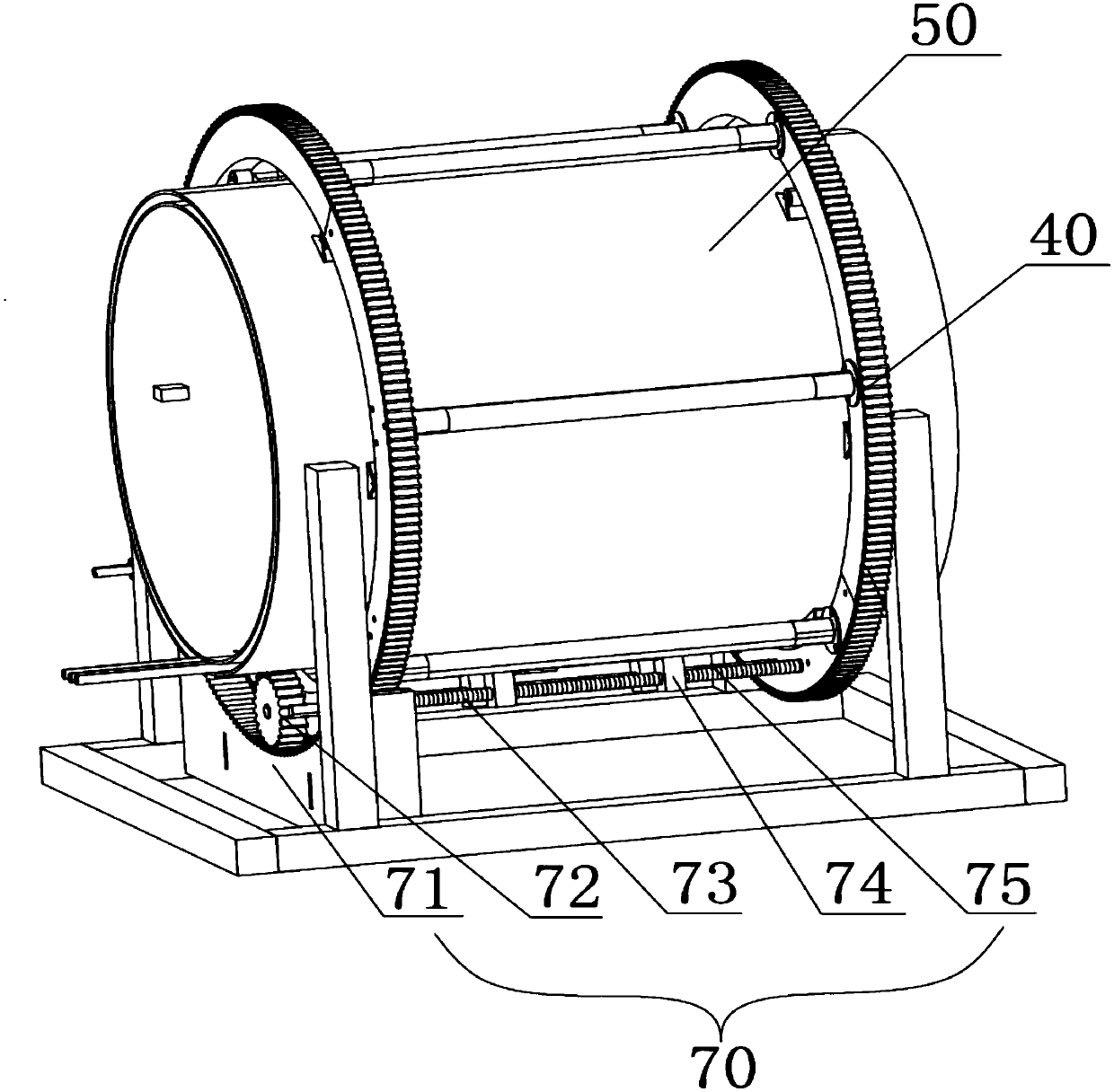
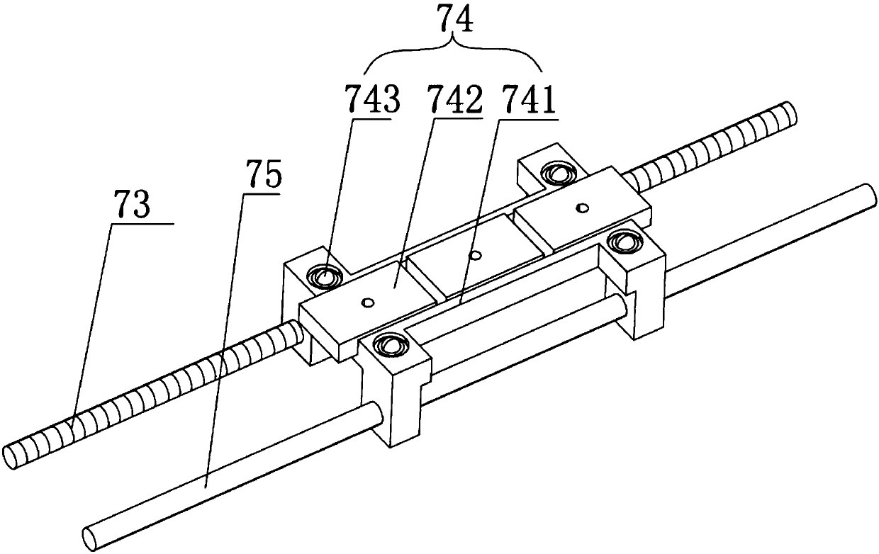
The invention relates to an intelligent magnetic traction type dust removing device for a flue and a control method thereof. The device includes an underframe, a transmission gear set, a driving motor, a transmission cage, a flue connection cylinder, a dust-removal scraper and an axial-direction transmission unit; the flue connection cylinder is fixed on the underframe and embedded in the transmission cage, the transmission gear set drives the transmission cage to rotate, and the axial-direction transmission unit includes an arc gear plate, a screw rod transmission gear, a threaded rod and a magnet carrier; the threaded rod is arranged on the transmission cage, the screw rod transmission gear is fixedly connected with one end of the threaded rod, and the arc gear plate is fixed on the underframe; the dust-removal scraper is placed in the flue connection cylinder, and when the screw rod transmission gear is meshed with the arc gear plate, the magnet carrier drives the dust-removal scraper to do axial movement. According to the intelligent magnetic traction type dust removing device for the flue, the dust removal effect is good, no barriers are in the flue, and it is ensured that flue gas can be smoothly exhausted.

Description

technical field [0001] The invention relates to the technical field of dust removal equipment, in particular to an intelligent magnetic traction flue dust cleaning device and a control method thereof. Background technique [0002] In the current enterprises, a flue is usually installed in the combustion furnace and kiln to transport the flue gas and small particle dust generated during the combustion to the dust removal equipment. However, during use, some smoke and dust will continue to adhere to the inner wall of the flue. After long-term use, if the humidity of the flue gas is high and the temperature of the flue gas is lower than the acid dew point, the ash will scale on the wall of the flue. . If these scales accumulate over the years, the flue will be blocked, which will affect the emission of flue gas and the use of the combustion furnace. In order to prevent the dust in the flue gas from depositing in the flue, it is generally required that the flue gas flow rate of...

Claims


Application Information

Patent Timeline
Patent Type & Authority Patents(China)
IPC IPC(8): F23J3/02
CPCF23J3/026
Inventor 肖顺根宋萌萌杜金鑫杨志成杨奇恩
Owner HEFEI WISDOM DRAGON MACHINERY DESIGN CO LTD
Why Eureka
Try Eureka