
Compressible wall function calculation method considering boundary layer combustion heat release effect

A calculation method and boundary layer technology, applied in calculation, computer-aided design, electrical digital data processing, etc., can solve the problems of not considering the exothermic effect of chemical reaction, reducing the amount of calculation, and the difficulty of applying scramjet wall function method, etc. To achieve the effect of improving the efficiency of numerical simulation

Inactive Publication Date: 2017-10-24
BEIHANG UNIV
View PDF2 Cites 9 Cited by
  • Summary
  • Abstract
  • Description
  • Claims
  • Application Information

AI Technical Summary

Problems solved by technology

Therefore, the use of the wall function method can effectively relax the restrictions on the mesh density of the wall friction and heat flow simulation, thereby reducing the amount of calculation
The complexity of the flow in the scramjet brings great difficulties to the application of the wall function method: the combustion chemical reaction will occur in the compressible turbulent boundary layer. A large number of experiments and numerical simulation studies at home and abroad have shown that the turbulent boundary layer The combustion heat release effect will greatly change the wall friction and heat flow, so the combustion heat release effect in the boundary layer must be considered in the wall function model
However, all existing wall function methods at home and abroad are based on the assumption that there is no chemical reaction in the boundary layer. At present, there is no wall function model that considers the exothermic effect of chemical reactions in the boundary layer, which also makes the wall function method unable to be applied. In the friction / heat flow simulation of scramjet inner runner

Method used


Image

  • Compressible wall function calculation method considering boundary layer combustion heat release effect
  • Compressible wall function calculation method considering boundary layer combustion heat release effect
  • Compressible wall function calculation method considering boundary layer combustion heat release effect

Examples


Embodiment

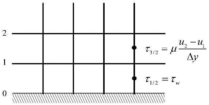
[0062] Embodiment: Based on the compressible wall function method considering the boundary layer combustion heat release effect proposed in the present invention, for Figure 4 An experimental case shown involving boundary layer combustion was simulated. Air flow conditions are: Mach number 4.42, temperature 1120K, pressure 83kPa. Hydrogen is injected into the supersonic compressible turbulent boundary layer formed by air at the speed of sound through a step with a height of 3mm on the upper wall, Figure 5 The temperature distribution nephogram obtained from the calculation given in can see the diffusion combustion flame formed in the boundary layer. Figure 6 Firstly, it is shown that in the dense grid (the grid scale of the first layer of the wall is 5×10 -7 m, the corresponding y + Comparing the ratio of friction resistance and heat flow with / without boundary layer combustion calculated without using wall function under the condition of about 1) with the experimental da...


PUM


Abstract

The invention discloses a compressible wall function calculation method considering a boundary layer combustion heat release effect, and belongs to the field of computational fluid mechanics. A velocity wall law and a temperature wall law under a combustion chemical reaction condition are proposed through theoretical derivation; based on this, a unified wall function calculation method capable of being compatible with compressible turbulent boundary layers with / without a chemical reaction simultaneously is established; and a detailed process coupled with a CFD program for solving is designed. The calculation method is low in technical realization difficulty and is suitable for the condition with or without the boundary layer combustion heat release effect. The numerical simulation efficiency of frictional resistance / heat flow of a flow passage in a scramjet engine can be greatly improved, so that the calculation cycle is greatly shortened.

Description

technical field [0001] The invention belongs to the field of computational fluid dynamics (CFD), and in particular relates to a compressible wall function calculation method considering the combustion heat release effect of a boundary layer, which can effectively improve the calculation efficiency of friction resistance / heat flow in a scramjet internal flow channel. Background technique [0002] The scramjet engine is considered to be an ideal power plant for future air-breathing hypersonic vehicles, and its technological development has great strategic significance, so it has received great attention from various countries. Due to the difficulty in implementing experiments related to supersonic combustion and the fact that some parameters cannot be directly obtained due to the limitation of measurement techniques, computational fluid dynamics (CFD) has been widely used in the flow field analysis of scramjet inner flow channels, and has gradually become a Very important tech...

Claims


Application Information

Patent Timeline
IPC IPC(8): G06F17/50
CPCG06F30/20G06F2119/06G06F2119/08
Inventor 高振勋蒋崇文李椿萱张智超
Owner BEIHANG UNIV
Learn More