


Quick Research
Generate reliable direction feasibility study reports for your R&D in just a few steps.

Technical Q&A
Discover and master advanced knowledge NOW. Basics, ideas, possibilities, all at once.

Find Solutions
As an expert in R&D theories, this can generate solutions to your technical problems instantly.

Evaluate Feasibility
Analyze your overall solution with one click, know your potential R&D risks in advance.

Monitor Landscape
Get weekly tech updates, stay abreast of the latest tech innovations and key insights.
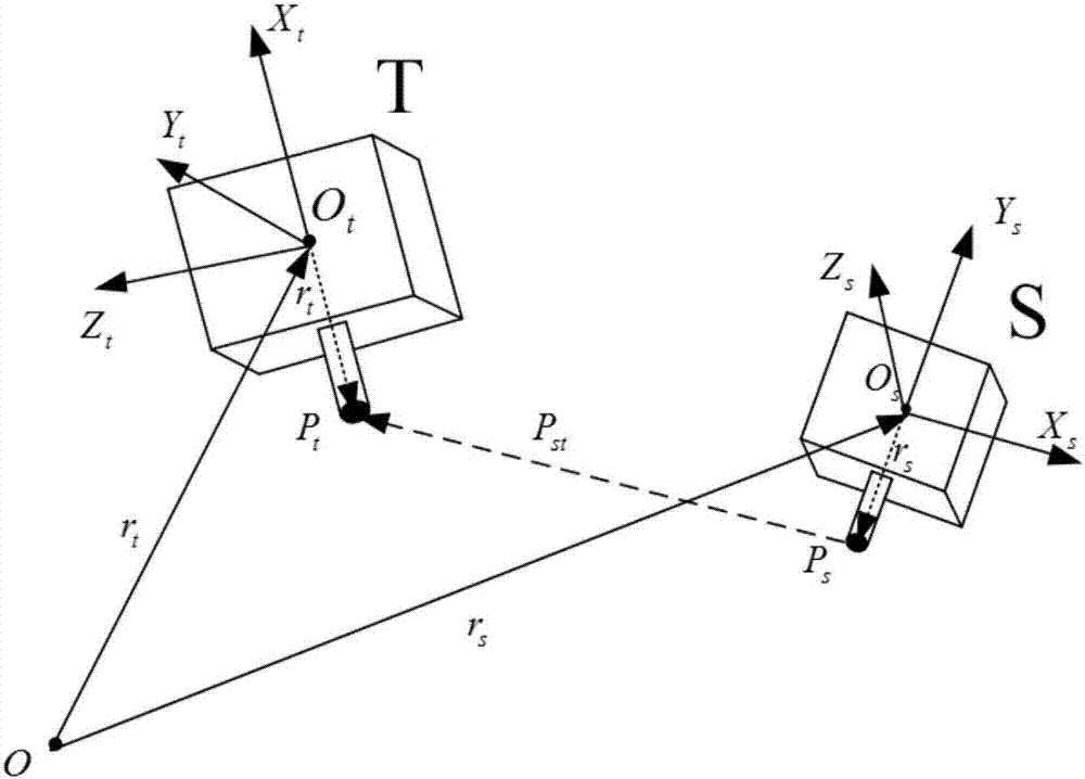
Spacecraft non-centroid relative movement modeling method
A technology of relative motion and modeling methods, applied in the direction of instruments, adaptive control, control/regulation systems, etc., can solve problems such as reducing the efficiency of task completion
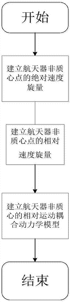
- Summary
- Abstract
- Description
- Claims
- Application Information
AI Technical Summary
Problems solved by technology
Method used
Image

Examples
Embodiment
[0088] The simulation background is designed as the close rendezvous stage of the spacecraft on orbit. Here, it is assumed that the target spacecraft is flying in orbit without maneuvering, and in order to facilitate the calculation of the projection of its velocity screw in its own system, the main axis of the body coordinate system of the target spacecraft is consistent with the main axis of the orbit coordinate system during operation, and its The parameter setting of the motion track is shown in Table 1:
[0089] Table 1. Orbital parameters of the target spacecraft
[0090] Number of six tracks
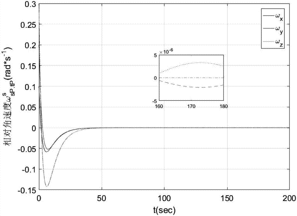
[0091] Both mass and moment of inertia are real values and remain constant. Using the non-centroid relative motion attitude-orbit coupling model established by the present invention, the attitude-orbit coupling control in the rendezvous process is carried out, and the simulation results are as follows Figure 3-Figure 8 As shown in the figure, it can be seen from the f...
PUM
 Abstract
Description
Claims
Application Information
 - R&D Engineer
- R&D Manager
- IP Professional
- Industry Leading Data Capabilities
- Powerful AI technology
- Patent DNA Extraction
Browse by: Latest US Patents, China's latest patents, Technical Efficacy Thesaurus, Application Domain, Technology Topic, Popular Technical Reports.
© 2024 PatSnap. All rights reserved.Legal|Privacy policy|Modern Slavery Act Transparency Statement|Sitemap|About US| Contact US: help@patsnap.com