
Power assisting device of steering system

A technology of a power assist device and a steering system, which is applied to steering mechanisms, mechanical steering gears, electric steering mechanisms, etc., can solve the problems of poor consistency of no-load rotational torque of worm gears, vibration noise, and machining deviations of worm gears and worms.

Inactive Publication Date: 2017-10-24
CHERY AUTOMOBILE CO LTD
View PDF5 Cites 4 Cited by
  • Summary
  • Abstract
  • Description
  • Claims
  • Application Information

AI Technical Summary

Problems solved by technology

When the vehicle is running normally, the wheels will transmit the alternating external force exerted by the road surface to the steering knuckle, tie rod and other components in time, and then transmit it to the worm gear reduction transmission mechanism that provides steering assistance, and the tooth surfaces of the worm gears that mesh with each other will appear. Wear and tear, this kind of wear will cause a gap between the meshing tooth surface of the rotating shaft core relative to the fixed worm gear and the worm, and the existence of this gap will give the pressure applied to the road surface to the worm gear reduction transmission mechanism through steering knuckles, tie rods and other components. Alternating external force provides opportunities for tooth surface impact vibration. On the one hand, this impact vibration will further damage the worm gear reduction transmission mechanism. On the other hand, it will generate vibration noise.
At the same time, when designing, it is inevitable that there will be machining deviations of worm gears, machining deviations of shell installation dimensions and assembly deviations, which will cause poor consistency of no-load rotational torque of worm gears and worms.

Method used


Image

  • Power assisting device of steering system
  • Power assisting device of steering system
  • Power assisting device of steering system

Examples


Embodiment Construction

[0012] Combine below Figure 1-Figure 7 The present invention is discussed in further detail.

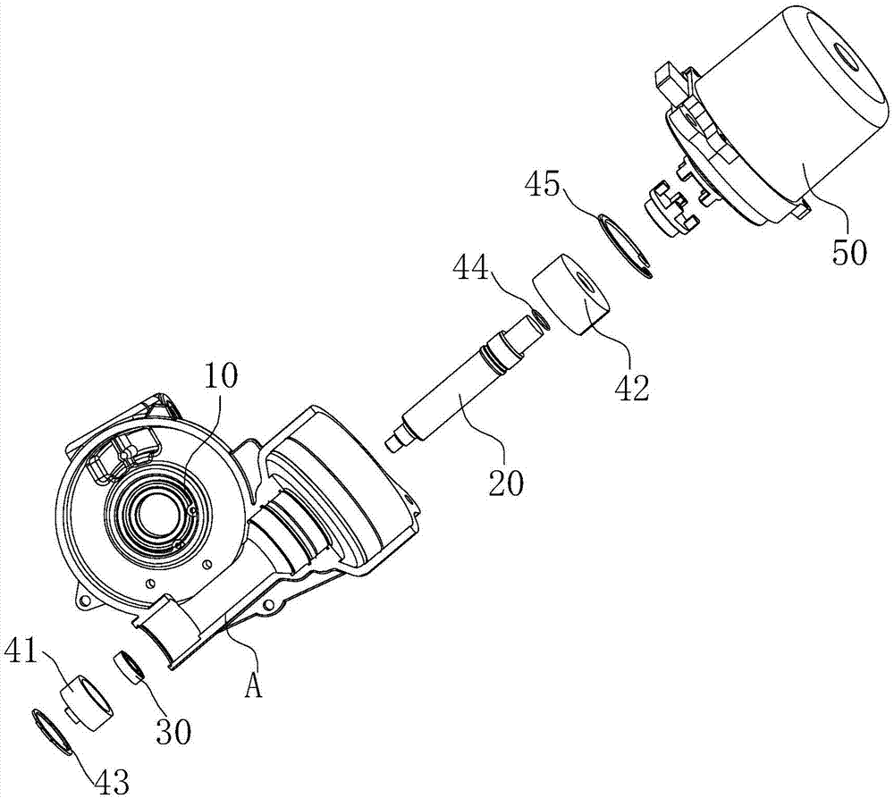
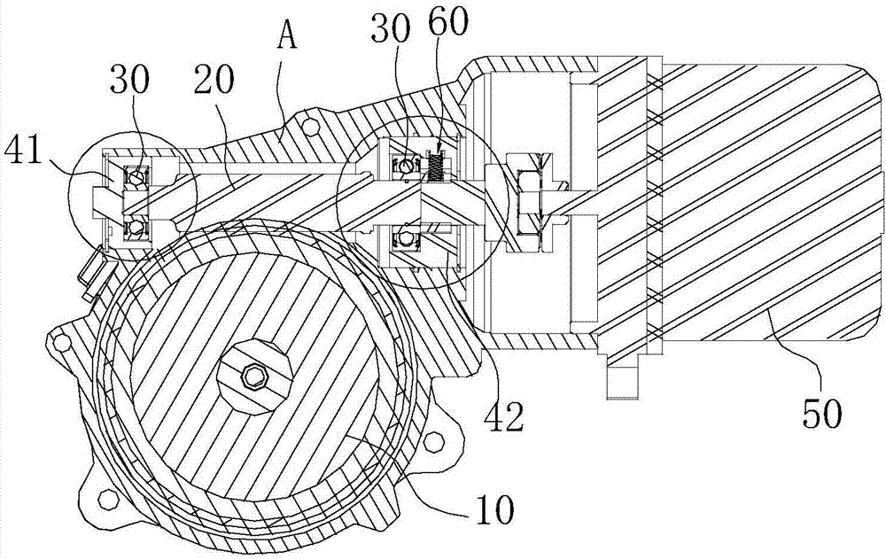
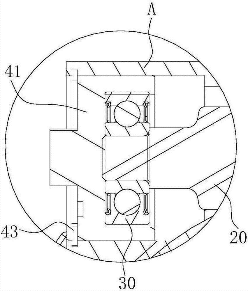
[0013] A power assist device for a steering system, comprising a worm gear 10 and a worm 20 meshing with each other, one end of the worm 20 is coaxially connected with the output shaft of the power assist motor 50, and the bearing 30 at the other end of the worm 20 is connected to the reducer housing A A first bearing seat 41 is disposed between them, and the bearing installation hole core of the first bearing seat 41 is eccentrically set with the outer circle center of the first bearing seat 41 . Rotating the first bearing seat 41 drives the worm 20 to press the worm wheel 10 . Since the inner cavity of the first bearing seat 41 is eccentrically arranged, when there is a machining tolerance, installation tolerance or wear gap between the worm wheel and the worm 10, 20, the first bearing seat 41 is rotated to drive the worm 20 closer to or away from the worm wheel 10, Adjust the no...


PUM


Abstract

The invention provides a power assisting device of a steering system. The power assisting device can adjust the unloading torque of a reducing mechanism and compensate the wearing clearance between a worm and a gear. The power assisting device comprises the worm and the gear which are engaged with each other, one end of the worm is coaxially connected with an output shaft of a power assisting motor, a first bearing block is arranged between a bearing at the other end of the worm and a reducer shell, a bearing mounting hole core of the first bearing block and the center of an outer circle of the first bearing block are eccentric, the first bearing block rotates, and the worm is driven to compress the gear. As an inner cavity of the first bearing block is eccentric, when the machining tolerance, mounting tolerance or wearing clearance occurs between the worm and the gear, the first bearing block rotates, the worm is driven to be close to or far away from the gear, the unloading rotation torque of the worm and the gear is adjusted, normal engagement of the worm and the gear is ensured, and engaging stability of the worm and the gear is improved and kept.

Description

technical field [0001] The invention relates to the technical field of steering systems for passenger cars, in particular to a power assist device for a steering system. Background technique [0002] At present, the so-called hydraulic resistance or electric power steering system has been widely used in various vehicles due to its convenient control, quick response and low energy consumption. Features, the scope of use of electric power steering is gradually expanding. The electric power steering system is mainly driven by a motor to rotate the worm in the worm gear reduction transmission mechanism. According to the installation position of the motor, it is divided into steering shaft type, gear assist type and rack assist type. When the vehicle is running normally, the wheels will transmit the alternating external force exerted by the road surface to the steering knuckle, tie rod and other components in time, and then transmit it to the worm gear reduction transmission mec...

Claims


Application Information

Patent Timeline
Patent Type & Authority Applications(China)
IPC IPC(8): B62D3/04B62D5/04
CPCB62D3/04B62D5/0421
Inventor 郑正高家兵刘慧建陶薛磊卢兴运王晓云裴福兴
Owner CHERY AUTOMOBILE CO LTD
Learn More