A tail gas treating device and method
A technology for tail gas treatment and filtration device, which is applied in separation methods, chemical instruments and methods, and dispersed particle separation, etc., can solve the problem that the toxic sediment particles in the tail gas cannot be rapidly cooled, precipitated and collected, and achieves space saving, efficient cleaning and cleaning. Collect and reduce the effect of device interfaces
- Summary
- Abstract
- Description
- Claims
- Application Information
AI Technical Summary
Problems solved by technology
Method used
Image

Examples
Embodiment 1
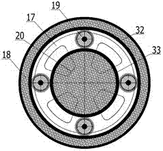
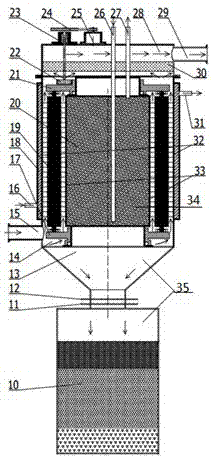
[0027] This embodiment relates to an exhaust gas treatment device, such as Figure 2-3 As shown, the exhaust gas treatment device includes an intake chamber 15, a cooling deposition chamber 34, and an exhaust chamber 29 from bottom to top. The intake chamber 15 is located below the cooling deposition chamber 34, and the cooling deposition chamber 34 is provided with a cooling cylinder 20 inside. A deposition chamber 14 is formed between the outer wall 33 of the cooling cylinder and the inner wall of the cooling deposition chamber 34. The deposition chamber 14 is provided with one or more particle cleaning mechanisms for cleaning the outer wall 33 of the cooling cylinder and the inner wall of the cooling deposition chamber 34.
[0028] Preferably, the particle cleaning mechanism in this embodiment is a roller brush 19, the upper end of the roller brush 19 is connected to the upper planet carrier 21, and the stepping motor 25 controls the upper planet carrier through the belt convey...
Embodiment 2
[0035] This embodiment relates to an exhaust gas treatment device. The exhaust gas treatment device of this embodiment is based on the device of the foregoing embodiment 1. A collection part 35 is provided below the cooling deposition chamber 34, and the collection part 35 is in communication with the bottom of the cooling deposition chamber 34 , That is, the collecting part 35 is located below the deposition chamber 14 to realize online collection of deposited particles.
[0036] Preferably, in this embodiment, the collection part 35 includes a collection chamber 13 and a collection bucket 10 from top to bottom, and is provided with a collection chamber valve 12 and a collection bucket valve 11, and the collection chamber 13 is in the shape of a funnel, and the deposited particles fall into The inclined surface of the funnel-shaped collection chamber 13 will enter the collection bucket 10 without causing accumulation. The simultaneous existence of the collection chamber valve 12 ...
Embodiment 3
[0039] This embodiment relates to an exhaust gas processing method, which uses a cooling deposition chamber to cool and deposit the exhaust gas, and at the same time clean the deposited particles; and use a collecting part connected to the lower part of the cooling deposition chamber to collect and clean the deposited particles.
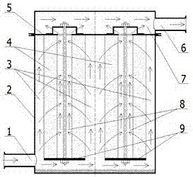
[0040] Preferably, while cleaning the deposited particles, a filter device connected to the upper part of the cooling deposition chamber is also used to filter the cooled and deposited exhaust gas.
[0041] Specifically, after the tail gas of the MOCVD equipment enters the cooling deposition chamber, under the cooling effect of the cooling deposition chamber, the deposited particles of the tail gas are precipitated and cleaned to the collecting part communicating with the lower part of the cooling deposition chamber. At the same time, the exhaust gas after the cooling deposition enters and The filter device connected above the cooling deposition chamber is...
PUM
 Abstract
Description
Claims
Application Information
 - Generate Ideas
- Intellectual Property
- Life Sciences
- Materials
- Tech Scout
- Unparalleled Data Quality
- Higher Quality Content
- 60% Fewer Hallucinations
Browse by: Latest US Patents, China's latest patents, Technical Efficacy Thesaurus, Application Domain, Technology Topic, Popular Technical Reports.
© 2025 PatSnap. All rights reserved.Legal|Privacy policy|Modern Slavery Act Transparency Statement|Sitemap|About US| Contact US: help@patsnap.com