Uni and bi-direction power load counterweight resistance element device

A dynamic load and resistance technology, applied in the direction of electromechanical devices, sports accessories, electrical components, etc., can solve the problems of operator injury and safety hazards, and achieve the effects of improving integrity, adjustable damping effect, and significant damping buffer effect

Inactive Publication Date: 2017-10-24
张孟迪
View PDF6 Cites 2 Cited by
  • Summary
  • Abstract
  • Description
  • Claims
  • Application Information

AI Technical Summary

Problems solved by technology

[0002] The outdoor fitness equipment that exists in existing life has great potential safety hazards. For example, there is no limit to the movable part, which can rotate 360 ​​degrees in the axial direction, and the increase of the reciprocating force of the movement will easily cause physical injury to the operator during the use of the equipment.

Method used


Image

  • Uni and bi-direction power load counterweight resistance element device
  • Uni and bi-direction power load counterweight resistance element device
  • Uni and bi-direction power load counterweight resistance element device

Examples


Embodiment 1

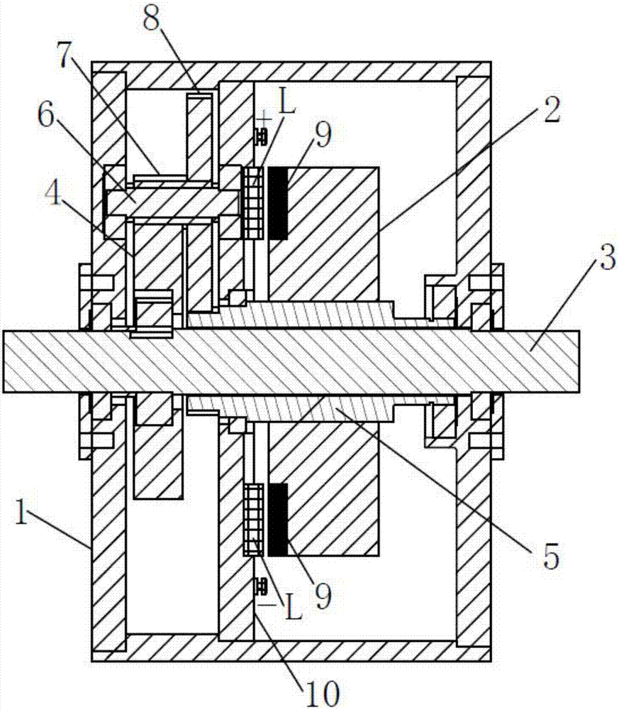
[0021] Depend on figure 1 , 2 It can be known from the embodiment shown in and 4 that this embodiment includes a transmission component support body 1, a gear transmission connection structure and at least one damping counterweight 2, and the gear transmission connection structure includes a drive gear shaft and a drive gear shaft for axially fixed connection with the damping action shaft. The gear transmission part, the driving gear shaft includes the driving shaft 3 and the driving gear 4, the driving gear 4 is fixed on the driving shaft 3, the driving gear shaft and each gear transmission parts are respectively supported on the transmission part support body 1 through bearings, and the driving gear 4 It forms a gear meshing transmission connection with each gear transmission part. The gear transmission part at the end of the gear transmission connection structure is connected to the damping weight 2 gear meshing transmission connection. The damping weight 2 is a rotating bo...

Embodiment 2

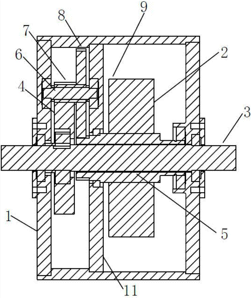
[0029] Depend on image 3 and 4It can be seen from the illustrated embodiment that this embodiment includes a transmission component support body 1, a gear transmission connection structure and at least one damping counterweight 2, and the gear transmission connection structure includes a drive gear shaft and a gear transmission shaft for axially fixed connection with the damping shaft. Components, the driving gear shaft includes a driving shaft 3 and a driving gear 4, the driving gear 4 is fixed on the driving shaft 3, the driving gear shaft and each gear transmission part are respectively supported on the transmission part support body 1 through bearings, and the driving gear 4 and each A gear meshing transmission connection is formed between the gear transmission parts, and the gear transmission part at the end of the gear transmission connection structure is connected to the gear meshing transmission connection of the damping weight 2, the damping weight 2 is a rotating bo...


PUM


Abstract

The invention discloses a uni and bi-direction power load counterweight resistance element device comprising a transmission part support body, a gear transmission connection structure and at least one damping counterweight. The gear transmission connection structure comprises a driving gear shaft for being axially and fixedly connected with a damping action shaft, and gear transmission parts. The driving gear shaft comprises a driving shaft and driving gear. The driving gear is fixed on the driving shaft. The driving gear shaft and each gear transmission part are respectively supported on the transmission part support body via bearings. Gear engagement transmission connection is formed between the driving gear and each gear transmission part. The gear transmission part at the tail end of the gear transmission connection structure is in gear engagement and transmission connection with the damping counterweights. Each damping counterweight is a revolving body. The ratio of driving shaft rotating speed and damping counterweight rotating speed is less than 1. The uni and bi-direction power load counterweight resistance element device has the characteristics that the structure is compact, the damping and buffering effect is significant, and the damping effect is adjustable.

Description

technical field [0001] The invention relates to a unidirectional and bidirectional power load counterweight resistance element device. Background technique [0002] The outdoor fitness equipment that exists in existing life has great potential safety hazards. For example, there is no limit to the movable parts, which can rotate 360 ​​degrees in the axial direction. The increase of the reciprocating force of the movement can easily cause physical injury to the operator during the use of the equipment. Contents of the invention [0003] The technical problem to be solved by the present invention is to provide a unidirectional and bidirectional power load counterweight resistance unit device, which has the characteristics of compact structure and remarkable damping and buffering effect. [0004] In order to solve the problems of the technologies described above, the technical solution adopted in the present invention is: [0005] A single-bidirectional dynamic load counterwe...

Claims


Application Information

Patent Timeline
Patent Type & Authority Applications(China)
IPC IPC(8): A63B21/22A63B21/005H02K53/00
CPCA63B21/0052A63B21/222H02K53/00
Inventor 张孟迪
Owner 张孟迪
Why Eureka
Try Eureka