
Auto focus, multi-focal plane vr display system

A display system and auto-focusing technology, applied in optical components, instruments, optics, etc., can solve problems such as dizziness, single screen with optical path structure, etc., and achieve the effect of reducing dizziness and visual conflict.

Active Publication Date: 2019-10-25
JINHUA VRSEEN TECH
View PDF5 Cites 0 Cited by
  • Summary
  • Abstract
  • Description
  • Claims
  • Application Information

AI Technical Summary

Problems solved by technology

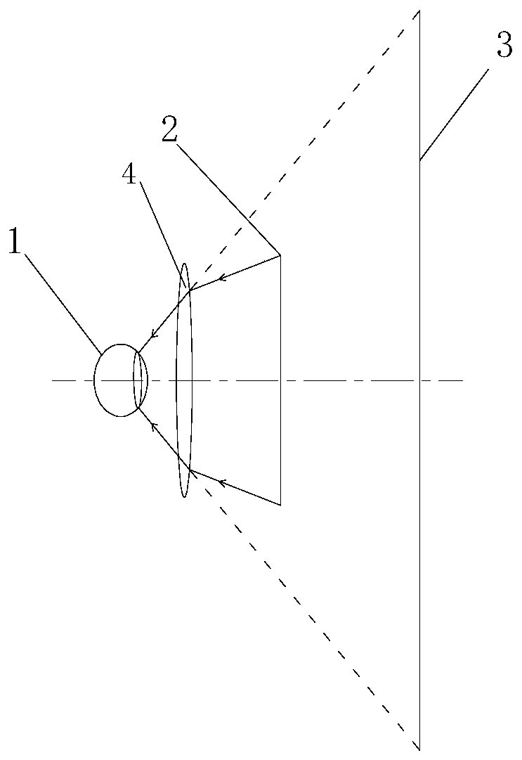
[0005] The optical path structure in existing VR helmets is illuminated by a single screen, such as figure 1 As shown, the lens 4 enlarges the image of the second screen 6 and enters the human eye 1, so the virtual images 3 seen by people are all on the same plane behind the second screen 6, so the virtual images themselves have no sense of hierarchy, just can cause dizziness

Method used


Image

  • Auto focus, multi-focal plane vr display system
  • Auto focus, multi-focal plane vr display system
  • Auto focus, multi-focal plane vr display system

Examples


Embodiment 1

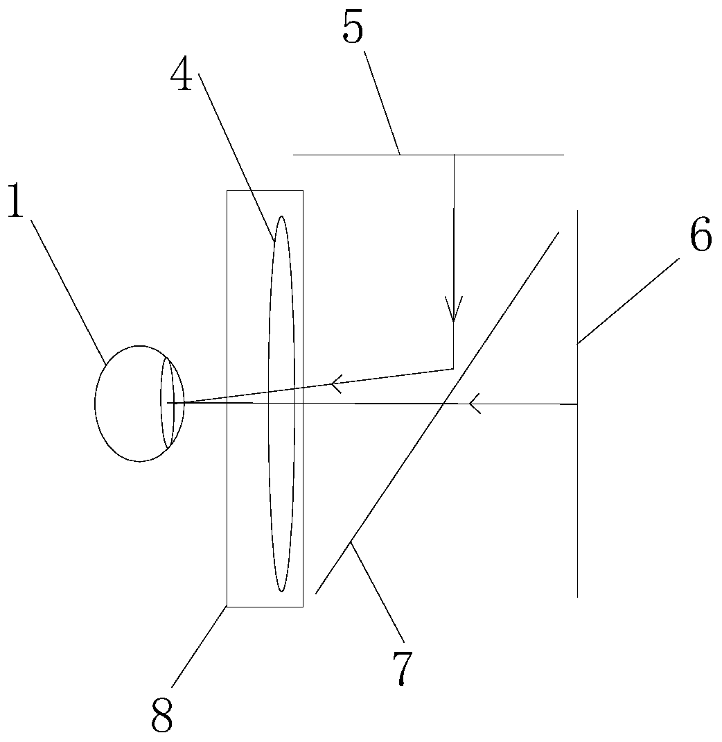
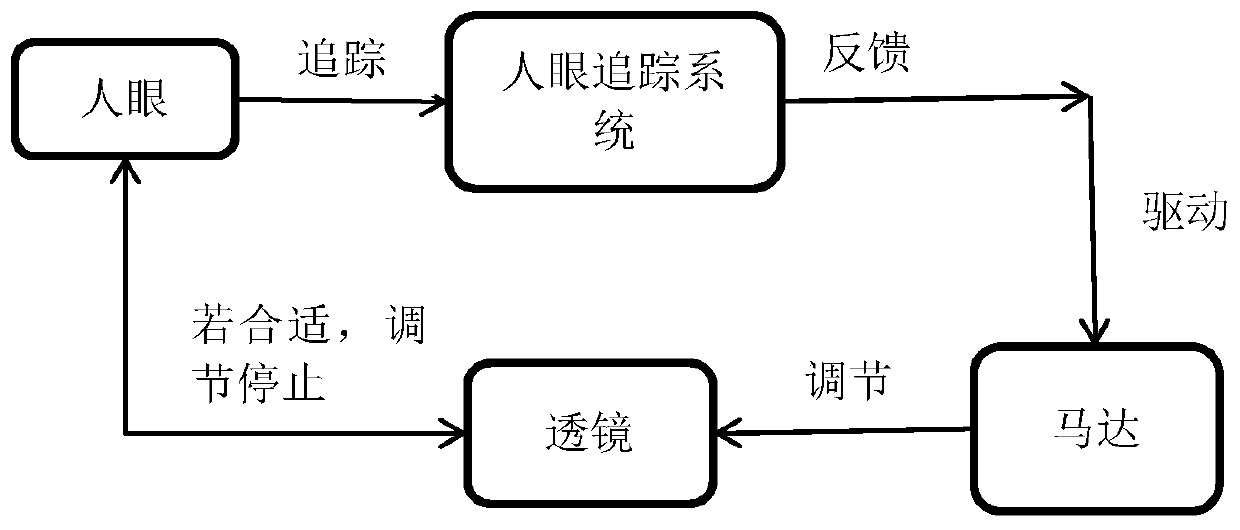
[0031] like figure 2 As shown, human eye 1, lens 4, first screen 5, second screen 6 and polarized reflective sheet 7 are included, lens 4, polarized reflective sheet 7 and second screen 6 are arranged in sequence on the same optical axis, and polarized reflective sheet 7 A first screen 5 is arranged on the side, and the human eye 1 is located in front of the second screen 6, and an eye tracking system is also provided directly in front of the human eye 1, and a motor 8 is connected to the lens 4; the first screen 5 is located beside the polarizing reflective sheet 7 , the second screen 6 is located on the positive side of the polarizing reflective sheet 7, the light emitted by the first screen 5 is reflected by the polarized reflective sheet 7 and then enters the human eye 1 through the lens 4, and the light emitted by the second screen 6 is transmitted through the polarized reflective sheet 7 Then enter the human eye 1 through the lens 4.

[0032] By setting up two sets of ...

Embodiment 2

[0039] like figure 2 Shown, overall structure is the same as embodiment 1, and difference is:

[0040] It is not necessary to display the near and far objects in the image on the first screen 5 and the second screen 6 respectively, but let the content displayed on the first screen 5 and the second screen 6 be basically the same, but the content displayed on each screen needs to be Do different blur position processing: make the close objects displayed on the first screen 5 clear, and the distant objects blurred; the near objects displayed on the second screen 6 are blurred, and the distant objects are clear.

[0041] When focusing on the first screen 5, only nearby objects can be seen clearly, and distant objects are blurred, while the second screen 6 is in a defocused state as a whole, and the entire image is blurred, and the nearby objects are clear when superimposed The purpose of blurring distant objects; also when focusing on the second screen 6 .

[0042] like image...


PUM


Abstract

The present invention discloses an automatic focusing and multi-focal plane VR display system. The system comprises eyes, a lens, a first screen, a second screen and a polarization reflection plate. The lens, the polarization reflection plate and the second screen are arranged in order along the same optical axis, the first screen is arranged at the side of the polarization reflection plate, and the eyes are located at the front of the second screen; the first screen and the second screen are respectively located at the side and the front of the polarization reflection plate, light emitted by the first screen and the second screen is subjected to light splitting through the polarization reflection plate to enter the eyes; and the light paths of the first screen and the second screen to the eyes are different, the position of the lens is regulated and moved along the optical axis to regulate the light path distances from the lens to the first screen and the second screen so as to change the focal plane of the eyes transmitting the lens and allow virtual images seen by the eyes to switch between the first screen and the second screen. The problem is solved that the amplitude regulation conflict caused by depth of field causes visual sense dizziness, and the visual sense conflict is greatly reduced so as to reduce the dizziness.

Description

technical field [0001] The present invention relates to a near-eye display system, and more specifically to an autofocus, multi-focal plane VR display system. Background technique [0002] At present, near-eye display devices are basically known to everyone, and commercialization, marketization, and productization are becoming more and more obvious. In particular, virtual reality (VR) technology with the characteristics of immersion, interaction, and conception is even more popular, but it is still not fully developed. Accepted by the public, in the final analysis, there are still some bottleneck technologies, such as lack of content, expensive high-end equipment, bulky, dizziness, etc. Among them, dizziness is one of the most difficult bottlenecks that are eager to solve at present. [0003] There are many reasons for vertigo, such as refresh delay, motion sickness, image distortion, rhythm adjustment conflict caused by depth of field, focus disorder, etc., and the rhythm a...

Claims


Application Information

Patent Timeline
Patent Type & Authority Patents(China)
IPC IPC(8): G02B27/01
CPCG02B27/0101G02B27/0172G02B27/0179G02B2027/0187
Inventor 张国军许兵孙静
Owner JINHUA VRSEEN TECH
Learn More