Eureka AIR delivers breakthrough ideas for toughest innovation challenges, trusted by R&D personnel around the world.

Continuous ice particle jet flow washing device based on vortex tube

A technology of vortex tubes and ice pellets, which is applied in the direction of cleaning heat transfer devices, ice making, ice making, etc., can solve the problems of low automation, low cleaning intensity, complex structure, etc. large area effect

Inactive Publication Date: 2017-10-20
QINGDAO UNIV
View PDF9 Cites 5 Cited by
  • Summary
  • Abstract
  • Description
  • Claims
  • Application Information

AI Technical Summary

Problems solved by technology

[0006] Existing patent (201310206089 heat exchanger cleaning device) utilizes the vortex tube to realize the heat exchanger cleaning method of alternating cold and hot air rheological temperature cleaning and peeling off the dirt with strong adhesion. Due to the limitation of the physical properties of the air medium, the cleaning intensity is low; the existing patent (200710055348 Dry-type purging device for air-cooled radiators in large-scale air-cooling systems) Cleaning large-scale air-cooling systems using air jets containing washing beads requires a large number of auxiliary machines to feed and recover washing beads. The structure is complicated, the cost is high, and the degree of automation is low. Washing beads may stay in the gaps and corners of the equipment, causing secondary pollution, and there are limitations in automatic cleaning in conjunction with the traveling system

Method used


Image

  • Continuous ice particle jet flow washing device based on vortex tube

Examples


Embodiment Construction

[0016] The technical solution of the present invention will be described in detail below in conjunction with the accompanying drawings, and the content of the present invention will be illustrated by means of the following examples, rather than limiting the scope of the present invention.

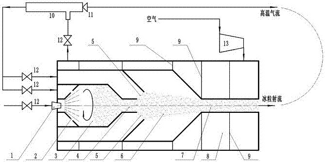
[0017] Such as figure 1 The shown continuous ice particle jet cleaning device based on vortex tube includes atomizing nozzle 1, swirl nozzle 2, ice making chamber 3, hollow tube 4, hollow circulation nozzle 5, mixing chamber 6, ice particle jet nozzle 7, pre- Cold cavity 8, swirl partition 9, cryogenic refrigerator 10, vortex tube regulating valve 11, valve 12 and compressor 13. The atomizing nozzle 1 and the swirl nozzle 2 are arranged in front of the ice-making chamber 3, the atomizing nozzle 1 is arranged in the center, the swirl nozzle 1 is arranged around the atomizing nozzle 1, and a hollow pipe 4 is arranged at the end of the ice-making chamber 3, and the hollow pipe 4 The outside i...


PUM


Abstract

The invention provides a continuous ice particle jet flow washing device based on a vortex tube. The continuous ice particle jet flow washing device based on a vortex tube mainly comprises an atomizing nozzle, a swirl nozzle, an ice making chamber, a hollow tube, a hollow circulation nozzle, a mixing chamber, an ice particle jet flow nozzle, a pre-cooling cavity, the vortex tube and the like. The continuous ice particle jet flow washing device carries out refrigeration through the vortex tube and is simple in structure, small in volume, low in weight and convenient to use. Ice particle jet flow and high-temperature airflow alternately spray a heat dissipation surface, and online washing is completed. Water is atomized through the atomizing nozzle to form water drops, the swirl nozzle carries out swirl mixing in the ice making chamber to form ice particles in a freezing manner, through the jetting, entrainment and mixing effects of the hollow circulation nozzle, the ice particles are further frozen and shaped in the mixing chamber, the strength of the ice particles is high, and the ice particle jet flow is sprayed through the ice particle jet flow nozzle. The pre-cooling chamber carries out pre-cooling to reduce the temperature, recovers the cooling capacity and reduces and eliminates low-temperature air flow heat loss, and energy sources are saved. The system can be applied to various surface washing and treating occasions, especially to finned radiators.

Description

technical field [0001] The invention relates to an ice particle jet cleaning device, in particular to a continuous ice particle jet cleaning device based on a vortex tube. Background technique [0002] The ice particle jet is formed by adding the prepared ice particles into the fluid jet. The ice particles also have a certain hardness and particle size at a very low temperature. The strength of the ice particle jet is 7 times that of the pure water jet under the same conditions. , It is far more than the strength of the air jet, and the cleaning effect is better. From the perspective of engineering applications, it has been successfully applied in industries such as surface cleaning, deburring of parts, rust removal, and food processing. [0003] The key to accelerating the industrial application of ice jet technology is to find a method that can continuously and instantly prepare ice particles with a certain temperature and particle size, reduce the storage of ice particle...

Claims


Application Information

Patent Timeline
Patent Type & Authority Applications(China)
IPC IPC(8): F28G1/16F28G15/00F25C1/00
CPCF25C1/00F28G1/163F28G15/00Y02P60/85
Inventor 郑艺华刘君
Owner QINGDAO UNIV
Why Eureka
Eureka Blog
Learn More