
Limiting and collision preventing structure of cooling refrigerator compressor

A refrigerator compressor, anti-collision technology, applied in mechanical equipment, machines/engines, liquid fuel engines, etc., can solve the problems of compressor influence, compressor stator and rotor gap offset, movement jamming, etc., to avoid metal powder , Guaranteed service life, the effect of broad application prospects

Active Publication Date: 2017-10-20
JIAXIPERA COMPRESSOR
View PDF6 Cites 8 Cited by
  • Summary
  • Abstract
  • Description
  • Claims
  • Application Information

AI Technical Summary

Problems solved by technology

The disadvantages of this structure are: 1. The limit groove can not limit the movement well, and the anti-collision point of the movement will fall off from the limit groove. Once it falls off, the movement will jam and cannot be reset.
2. The limit groove and the anti-collision point are all metal materials. During the long-term anti-collision collision process, metal powder will fall off, and enter the refrigeration cycle to affect the compressor and even the entire refrigerator refrigeration system, which will cause certain hidden dangers
3. Because the anti-collision point and the shell are all metal collisions, in the case of improper transportation and other links, the gap between the stator and rotor of the compressor will be offset, which will cause the compressor to start poorly due to poor gaps.

Method used


Image

  • Limiting and collision preventing structure of cooling refrigerator compressor
  • Limiting and collision preventing structure of cooling refrigerator compressor
  • Limiting and collision preventing structure of cooling refrigerator compressor

Examples


Embodiment 1

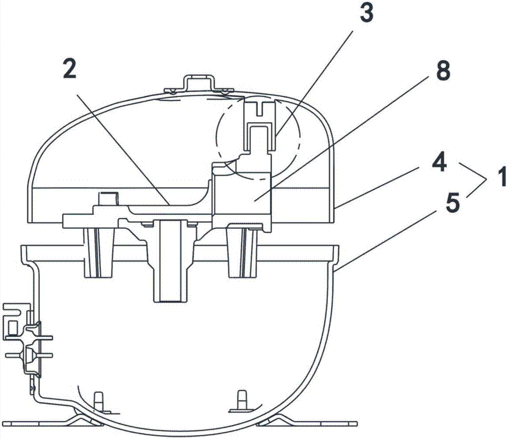
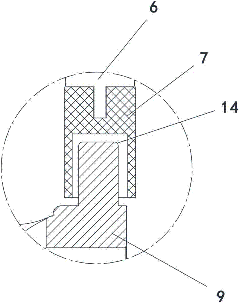
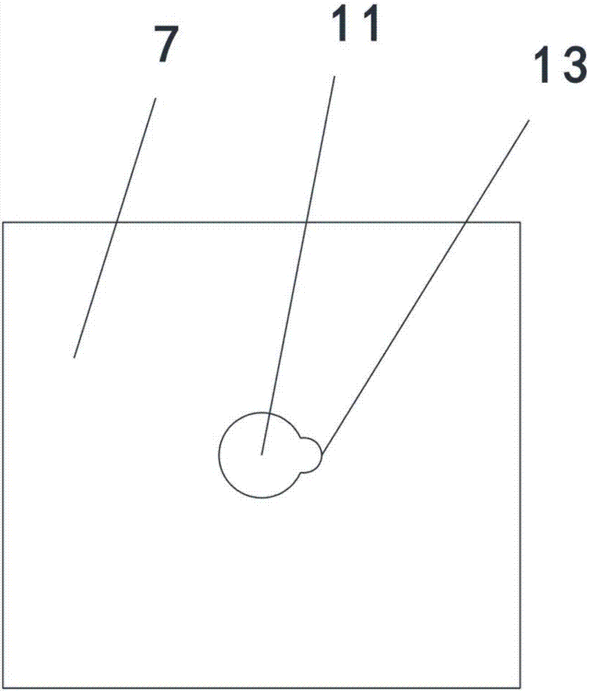
[0029] As an embodiment of the position-limiting and anti-collision structure of the refrigeration refrigerator compressor of the present invention, such as figure 1 , figure 2 , image 3 , Figure 4 and Figure 5 As shown, it includes a housing 1, a crankcase 2 and an anti-collision assembly 3, the crankcase 2 and the anti-collision assembly 3 are arranged inside the housing 1, and the anti-collision assembly 3 is arranged on the crankcase 2 Between the housing 1, the housing 1 includes an upper housing 4 and a lower housing 5, the anti-collision assembly 3 includes anti-collision studs 6 and anti-collision bushings 7, the crankcase 2 The upper part is provided with a crankcase cylinder head 8, and the upper part of the crankcase cylinder head 8 is provided with an anti-collision protrusion 9, and the lower surface of the anti-collision bushing 7 is provided with an anti-collision protrusion installation hole 10, and the anti-collision protrusion The anti-collision protr...

Embodiment 2

[0036] As an embodiment of the position-limiting and anti-collision structure of the refrigeration refrigerator compressor of the present invention, such as figure 1 , figure 2 , image 3 , Figure 4 and Figure 6 As shown, it includes a housing 1, a crankcase 2 and an anti-collision assembly 3, the crankcase 2 and the anti-collision assembly 3 are arranged inside the housing 1, and the anti-collision assembly 3 is arranged on the crankcase 2 Between the housing 1, the housing 1 includes an upper housing 4 and a lower housing 5, the anti-collision assembly 3 includes anti-collision studs 6 and anti-collision bushings 7, the crankcase 2 The upper part is provided with a crankcase cylinder head 8, and the upper part of the crankcase cylinder head 8 is provided with an anti-collision protrusion 9, and the lower surface of the anti-collision bushing 7 is provided with an anti-collision protrusion installation hole 10, and the anti-collision protrusion The anti-collision protr...

Embodiment 3

[0040] As an embodiment of the position-limiting and anti-collision structure of the refrigeration refrigerator compressor of the present invention, such as figure 1 , figure 2 , image 3 , Figure 4 and Figure 7 As shown, it includes a housing 1, a crankcase 2 and an anti-collision assembly 3, the crankcase 2 and the anti-collision assembly 3 are arranged inside the housing 1, and the anti-collision assembly 3 is arranged on the crankcase 2 Between the housing 1, the housing 1 includes an upper housing 4 and a lower housing 5, the anti-collision assembly 3 includes anti-collision studs 6 and anti-collision bushings 7, the crankcase 2 The upper part is provided with a crankcase cylinder head 8, and the upper part of the crankcase cylinder head 8 is provided with an anti-collision protrusion 9, and the lower surface of the anti-collision bushing 7 is provided with an anti-collision protrusion installation hole 10, and the anti-collision protrusion The anti-collision protr...


PUM


Abstract

The invention relates to the technical field of refrigerator cooling compressors, in particular to a limiting and collision preventing structure of a cooling refrigerator compressor. The limiting and collision preventing structure of the cooling refrigerator compressor comprises a shell, a crankcase and a collision preventing assembly. The crankcase and the collision preventing assembly are arranged in the shell. The collision preventing assembly is arranged between the crankcase and the shell. The shell comprises an upper shell body and a lower shell body. The collision preventing assembly comprises a collision preventing convex pin and a collision preventing bushing. A crankcase cylinder head is arranged on the upper portion of the crankcase. The upper portion of the crankcase cylinder head is provided with a collision preventing convex point. The lower surface of the collision preventing bushing is provided with a collision preventing convex point installation hole. The collision preventing convex pin is welded to the upper shell body. A collision preventing convex pin hole is formed in the upper surface of the collision prevention bushing. A semicircular edge is arranged on one side of the collision preventing convex pin. A semicircular clamping groove is formed in the collision preventing convex pin hole. The cross section of the collision preventing convex point is round or polygonal.

Description

technical field [0001] The invention relates to the technical field of refrigerator refrigeration compressors, in particular to a position-limiting and anti-collision structure of a refrigeration refrigerator compressor. Background technique [0002] The structure of the refrigeration compressor used in the current refrigerator is roughly assembled by the upper and lower shells and the inner core of the shell. The compressor will shake a lot during startup, shutdown or transportation, and some of the cores may even fall off the support spring. In order to prevent the machine core from colliding with the shell or falling off during transportation, the current common method is to design a limit groove on the upper shell of the compressor, cast an anti-collision point on the crankcase of the compressor core, and pass the anti-collision The cooperation of the point and the limit groove is used for collision prevention and limit. The disadvantages of this structure are: 1. The l...

Claims


Application Information

Patent Timeline
Patent Type & Authority Applications(China)
IPC IPC(8): F04C29/00
CPCF04C29/00F04C2240/80
Inventor 钱建忠史强杨骅王钊
Owner JIAXIPERA COMPRESSOR
Learn More