
Pipeline structure and rapid laying method for single-layer vacuum pipeline or double-layer vacuum pipeline of pipeline structure

A double-layer vacuum and vacuum pipeline technology, applied in the direction of roads, tracks, tunnel systems, etc., can solve the problems of high structural elastic modulus, high production cost, low erection efficiency, etc., and achieve low cost, convenient processing, and convenient and rapid erection. Effect

Active Publication Date: 2017-10-20
苏彬诚
View PDF7 Cites 5 Cited by
  • Summary
  • Abstract
  • Description
  • Claims
  • Application Information

AI Technical Summary

Problems solved by technology

[0004] Most of the pipe structures used in large-scale buildings in the prior art are formed by integral welding of metal plates, so there are many problems such as high structural elastic modulus, easy corrosion, and high production costs.
[0005] In addition, most of the vacuum pipes designed for high-speed trains in the prior art are also set up with metal pipes, so there are also the above defects, and there are also a series of problems such as poor sealing after erection and low erection efficiency.

Method used


Image

  • Pipeline structure and rapid laying method for single-layer vacuum pipeline or double-layer vacuum pipeline of pipeline structure
  • Pipeline structure and rapid laying method for single-layer vacuum pipeline or double-layer vacuum pipeline of pipeline structure
  • Pipeline structure and rapid laying method for single-layer vacuum pipeline or double-layer vacuum pipeline of pipeline structure

Examples


Embodiment Construction

[0027] The technical solutions of the present invention will be further described below in conjunction with the accompanying drawings and through specific implementation methods.

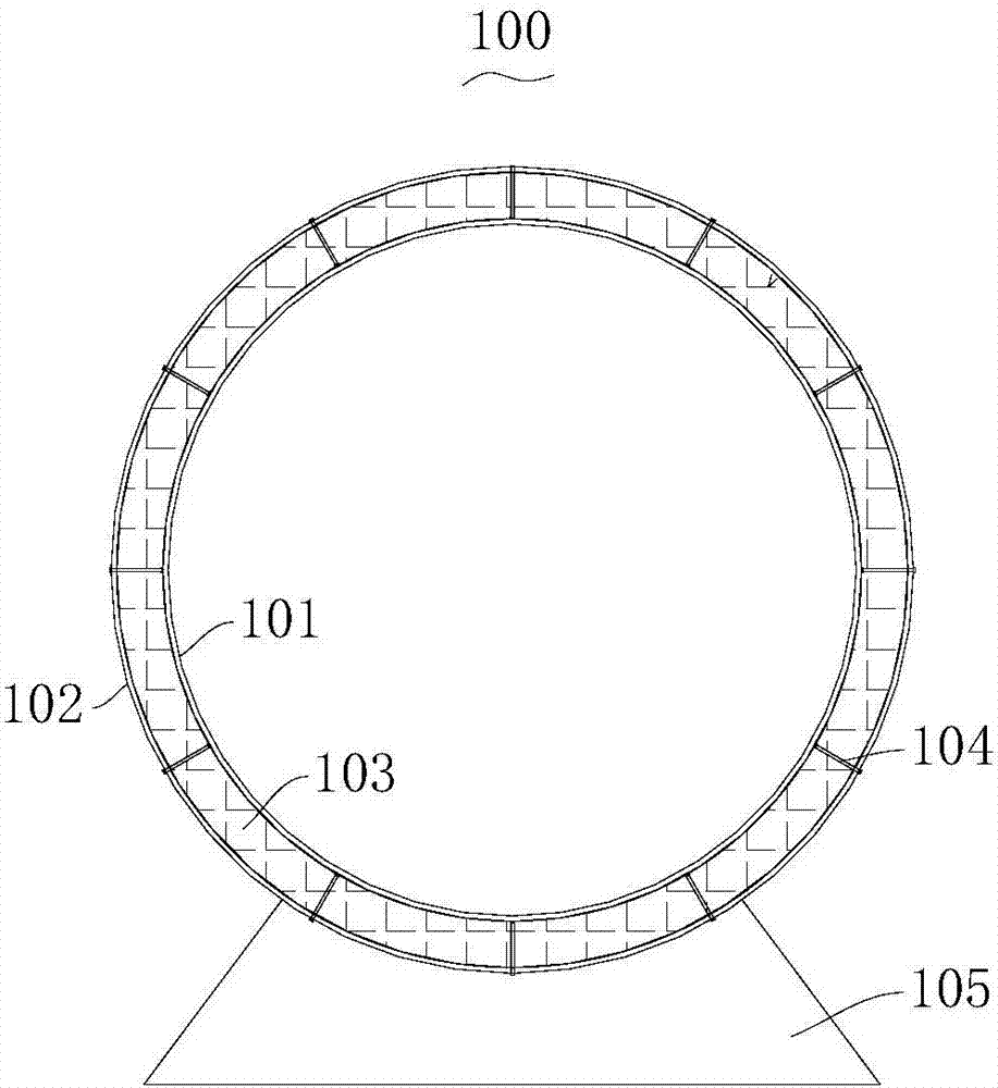
[0028] combine Figure 1 to Figure 2 As shown, this embodiment provides a pipeline structure, including an inner spiral tube 101, an outer spiral tube 102, and a high-strength rigid filling arranged between the inner layer spiral tube 101 and the outer layer spiral tube 102. material 103, and a tension member 104 for combining the inner layer spiral tube 101 and the outer layer spiral tube 102 with the hard filler 103, and the tension member 104 is respectively connected with the inner layer spiral tube 101 Fastened with the outer spiral tube 102, and the inner diameter of the inner spiral tube 101 is greater than or equal to 3m and less than or equal to 15m. In this embodiment, the inner diameter of the inner spiral tube 101 is preferably 6m.

[0029] In this embodiment, the inner spiral tube 101...


PUM


Abstract

The invention discloses a pipeline structure and a rapid laying method for a single-layer vacuum pipeline or a double-layer vacuum pipeline of the pipeline structure. The pipeline structure comprises an inner layer spiral pipe, an outer layer spiral pipe, a high-strength rigid filler arranged between the inner layer spiral pipe and the outer layer spiral pipe in a filled mode and a tensioning piece for combining the inner layer spiral pipe with the rigid filler as well as the outer layer spiral pipe with the rigid filler into a whole. The tensioning piece is fastened with the inner layer spiral pipe and / or the outer layer spiral pipe, and the inner diameter of the inner layer spiral pipe is larger than or equal to 3 m and is smaller than or equal to 15 m. According to the pipeline structure designed by using the structure, the pipe diameter is large, the pipeline strength is high, the cost is low, and processing is convenient; and the two pipelines in the structure are superimposed up and down, and a temporary conveying track and a permanent conveying track are arranged so that rapid erection of the single-layer vacuum pipeline or the double-layer vacuum pipeline can be conveniently realized, and the structure is stable and reliable.

Description

technical field [0001] The invention relates to the technical field of high-speed trains, in particular to a pipeline structure and a rapid laying method of a single-layer or double-layer vacuum pipeline. Background technique [0002] High-speed trains are the development direction of modern high-tech rail transportation. After the high-speed rail with wheel-rail technology reaches a speed of 400KM / h, there is no room for higher development due to the reduced friction between the wheels and rails. The way to achieve higher speed train running speed can also adopt the magnetic levitation system, which realizes the non-contact suspension and guidance between the train and the track through electromagnetic force, and then uses the electromagnetic force generated by the linear motor to pull the train to run. At present, the maglev train system can be divided into two directions, namely the constant conduction magnetic attraction (EMS) train adopted by Germany and the superconduc...

Claims


Application Information

Patent Timeline
Patent Type & Authority Applications(China)
IPC IPC(8): B61B13/08B61B13/10
CPCB61B13/08B61B13/10
Inventor 苏彬诚
Owner 苏彬诚
Learn More