
Novel braking structure of instructional car

A coach car, a new technology, applied in the field of coach cars, can solve problems such as inconvenient installation, potential safety hazards, and large brake device structure, and achieve the effect of small structure and convenient installation

Pending Publication Date: 2017-10-20
安徽嘻哈网络技术有限公司
View PDF5 Cites 2 Cited by
  • Summary
  • Abstract
  • Description
  • Claims
  • Application Information

AI Technical Summary

Problems solved by technology

At present, there are many functions, types and appearance styles of brake devices on the market. At present, the coach car basically adopts the pedal type man-machine control mechanical structure, that is, the brake device is connected with the main brake through the foot brake connecting rod, and then the brake device is fixed on the The auxiliary brake pedal, this structure restricts the layout space. When installing, because it can only be installed on the co-pilot, and the structure of the brake device is too large, it is inconvenient to install, and the coach sits in the co-pilot for a long time. The number of coaches is controlled, so that the coaches teach a large number of students for a long time, which will cause the coaches to work tired and leave potential safety hazards virtually.
[0003] As far as the current coaching car is concerned with the whole process of braking, it is usually three distances, that is, the driver's perceived reaction distance, braking distance, and braking effective (or pull belt) distance. The whole process of braking at a maximum speed of 40 kilometers per hour requires a braking distance of about 25 meters. In this way, the trainer car is driving at a high speed, and the students are not familiar with braking. When the coach is tired from work and encounters emergencies, it is inevitable that a crash will occur ACCIDENT

Method used


Image

  • Novel braking structure of instructional car
  • Novel braking structure of instructional car

Examples


Embodiment Construction

[0014] It will be apparent to those skilled in the art that the invention is not limited to the details of the above-described exemplary embodiments, but that the invention can be embodied in other specific forms without departing from the spirit or essential characteristics of the invention.

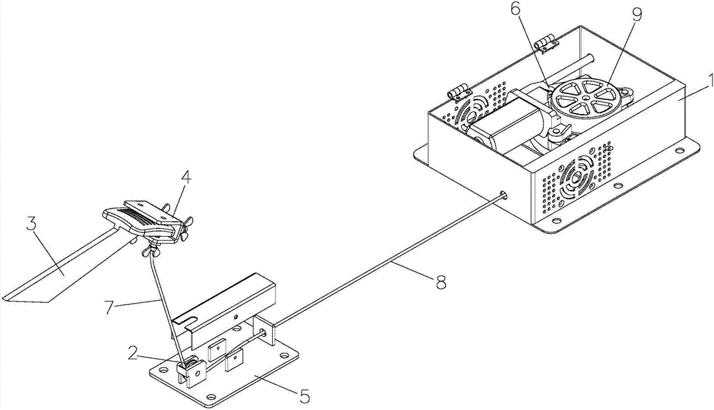
[0015] A new type of brake structure for a coach car, including a brake box 1, a reversing brake seat 5 and a locking mechanism 4 connected to the brake mechanism of the driver's cab of the coach car. The processing unit of the induction device controls the expansion and contraction of the telescopic mechanism 9, the telescopic end of the telescopic mechanism 9 is connected to the steel wire rope 7, and the telescopic mechanism 9 drives the steel wire rope 7 to expand and contract synchronously, and the extended end of the steel wire rope 7 passes through the reversing brake seat 5 and the locking mechanism 4 are fixedly connected, and a protective cover 8 is sleeved on the steel wire ro...


PUM


Abstract

The invention relates to a novel braking structure of an instructional car. The novel braking structure of the instructional car comprises a brake box, a reversing brake seat and a locking mechanism connected with a brake mechanism of a main cab of the instructional car; a telescopic mechanism is arranged inside the brake box; a processing unit of a radar sensing device on the instructional car controls the telescopic mechanism to stretch and contract; the telescopic end of the telescopic mechanism is connected with a steel wire rope; the telescopic mechanism stretches and contracts to drive the steel wire rope to stretch and contract synchronously; the externally stretching end of the steel wire rope penetrates through the reversing brake seat to be fixedly connected with the locking mechanism; and the position, between the brake box and the reversing brake seat, of the steel wire rope is sleeved with a protection sleeve. The novel braking structure of the instructional car is small, exquisite and simple in structure and convenient to install, and achieves intelligent mechanical operation, a coach does not need to sit on a co-driver seat all the time, the traditional structure that a brake device is arranged in the co-driver position is abandoned, the situation that the coach sits on the co-driver seat for a long time to cause fatigue teaching is avoided, potential safety hazards are eliminated, and the independent study capacity of trainees is improved.

Description

technical field [0001] The invention relates to a training vehicle, further relates to the improvement of brake safety control and auxiliary emergency braking of the training vehicle, and in particular relates to a new brake structure of the training vehicle. Background technique [0002] Now more and more private cars come into life, and the number of people learning to drive is increasing, so the safety and intelligence of coaches are getting more and more attention. Brake safety control and auxiliary emergency braking of the coach car are the guarantee of driving training safety. At present, there are many functions, types and appearance styles of brake devices on the market. At present, the coach car basically adopts the pedal type man-machine control mechanical structure, that is, the brake device is connected with the main brake through the foot brake connecting rod, and then the brake device is fixed on the The auxiliary brake pedal, this structure restricts the layo...

Claims


Application Information

Patent Timeline
Patent Type & Authority Applications(China)
IPC IPC(8): B60T7/22
CPCB60T7/22
Inventor 张全雷
Owner 安徽嘻哈网络技术有限公司
Learn More