
Electric vehicle charging system for charging through power transmission guide rail

An electric vehicle and charging system technology, applied in the direction of electric vehicle charging technology, electric vehicles, charging stations for charging mobile devices, etc., can solve the problems of long time required and the inability of electric vehicles to move.

Active Publication Date: 2017-10-20
GUANGZHOU LEYING INFORMATION TECH CO LTD
View PDF6 Cites 1 Cited by
  • Summary
  • Abstract
  • Description
  • Claims
  • Application Information

AI Technical Summary

Problems solved by technology

The existing charging methods are mainly charging piles, but due to the fixed installation position of the charging piles, electric vehicles can only be charged near the charging piles when charging; and the charging piles take a long time to charge, and electric vehicles cannot move when charging

Method used


Image

  • Electric vehicle charging system for charging through power transmission guide rail
  • Electric vehicle charging system for charging through power transmission guide rail
  • Electric vehicle charging system for charging through power transmission guide rail

Examples


Embodiment 1

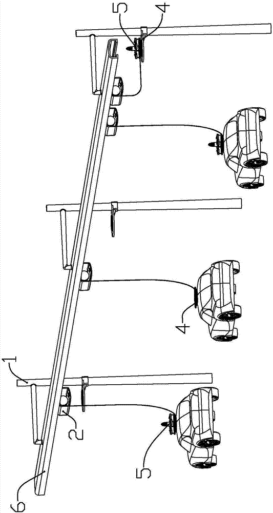
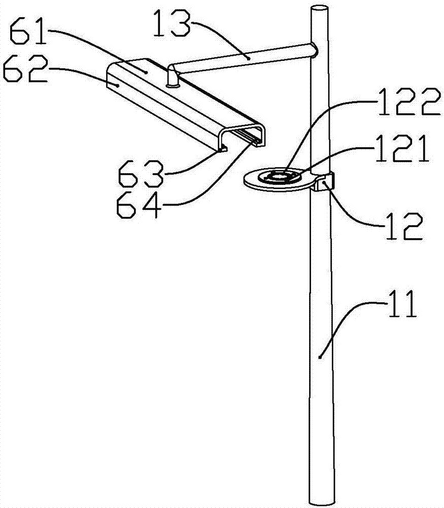
[0062] according to Figure 1 to Figure 19 As shown, the present embodiment is a charging system for an electric vehicle charged through a power transmission guide rail, including a plurality of utility poles 1 vertically installed equidistantly along the road beside the road, and a guide rail 6 fixedly installed on the utility pole above the road And a plurality of trolley assemblies 2 slidingly connected on the guide rail.

[0063] The trolley assembly includes a convex trolley frame 21, a winding assembly 22 slidably installed in the trolley frame, an end plate 23 fixedly connected to one end of the trolley frame, two slidingly connected in the trolley frame and inserted into the The electrode slide 24 in the winding assembly and the charging wire 25 spirally wound on the winding assembly.

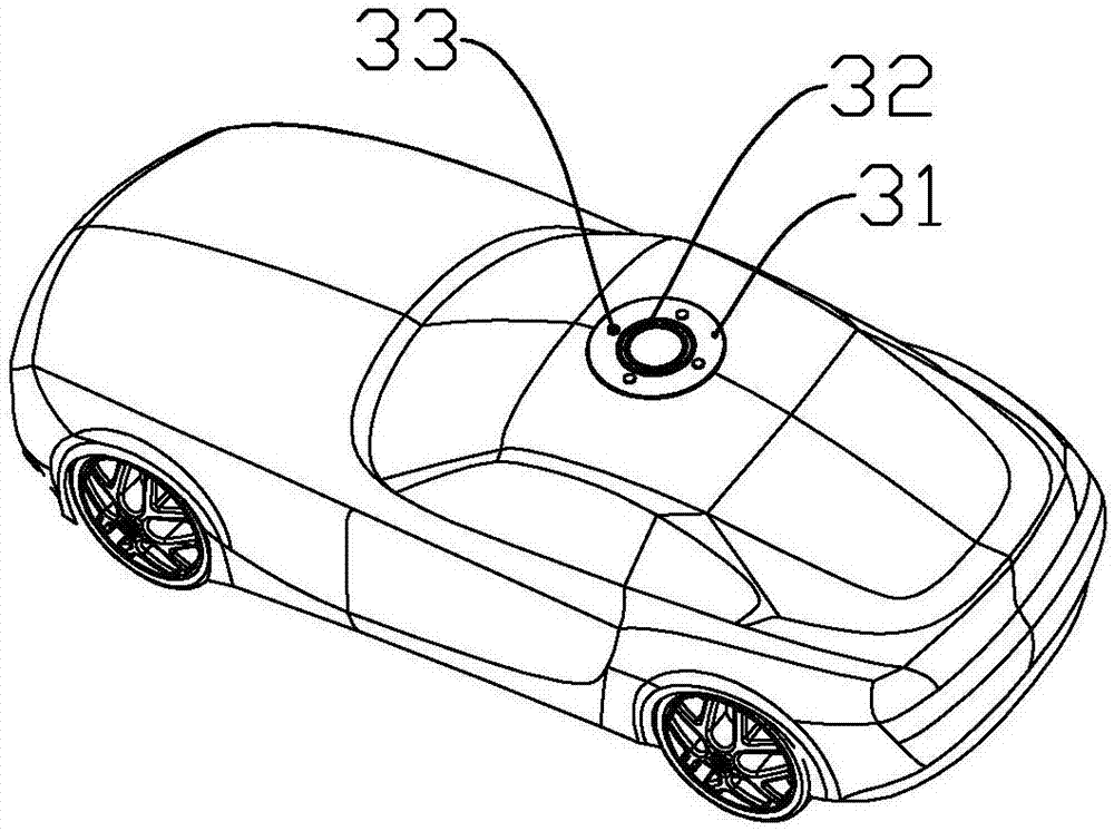
[0064] The end of the charging line is fixedly connected with a connecting pad 4 for charging the electric vehicle; the present invention also includes a plurality of aircraft 5 for ca...

Embodiment 2

[0101] This embodiment makes the following improvements on the basis of Embodiment 1: a landing gear joint 5110 is formed on the inner circumference of each of the air outlet rings away from the connecting pipe, and each of the landing gear joints is connected with a landing gear 53; The landing gear includes a connecting pipe body 531 that is fixedly connected with the landing gear joint and communicates with the inside of the air outlet ring through the landing gear joint, and a sliding pipe 532 that is slidably installed in the connecting pipe body and is connected with the connecting pipe body near the end of the landing gear joint. The supporting rod 535 connected by rotation is connected to the first electromagnet 536 on the supporting rod away from the end of the landing gear joint, and the connecting rod 534 which is respectively connected to the middle part of the sliding tube and the middle part of the supporting rod in rotation; The second receiving electrode 5361 fo...


PUM


Abstract

The invention belongs to the field of electric vehicle charging, and particularly relates to an electric vehicle charging system for charging through a power transmission guide rail. The electric vehicle charging system comprises a plurality of telegraph poles which are vertically and equidistantly mounted along roads, a guide rail which is fixedly mounted on the telegraph poles above the roads, a plurality of trolley assemblies which are connected to the guide rail in a sliding manner, connecting plates which are connected with the trolley assemblies, aircrafts which are movably connected to positions above the connecting plates, and electric vehicles which travel on the road. The electric vehicle charging system disclosed by the invention is arranged beside a road, so that the electric vehicles can be charged in time on the road without time limit; drivers can charge the electric vehicles while driving, so that the time that the drivers wait for charging the electric vehicle is saved; and the trolley assemblies are connected with the power transmission guide rail to supply power for the electric vehicles, so that the electric vehicle charging system is more flexible than charging piles, and charging places are not limited.

Description

technical field [0001] The invention belongs to the field of electric vehicle charging, and in particular relates to an electric vehicle charging system charged through a power transmission guide rail. Background technique [0002] As an energy-saving and environment-friendly vehicle, electric vehicles have outstanding advantages but also have problems in charging. The existing charging methods are mainly charging piles, but due to the fixed installation position of the charging piles, electric vehicles can only be charged near the charging piles when charging; and the charging piles take a long time to charge, and electric vehicles cannot be moved when charging. Contents of the invention [0003] The technical problem to be solved by the present invention is to provide a charging system for an electric vehicle that charges through a power transmission guide rail in view of the deficiencies in the prior art. [0004] In order to achieve the purpose of the present inventio...

Claims


Application Information

Patent Timeline
Patent Type & Authority Applications(China)
IPC IPC(8): B60L11/18H02J7/00
CPCB60L53/14B60L53/30B60L53/60B60M1/13B64C39/02H02J7/0027Y02T10/70Y02T10/7072Y02T90/12Y02T90/14
Inventor 虞丽丽江佳辉
Owner GUANGZHOU LEYING INFORMATION TECH CO LTD
Learn More