
A rail cutting machine shock absorber device

A shock-absorbing seat and cutting machine technology, which is applied in the direction of metal processing machinery parts, metal processing equipment, maintenance and safety accessories, etc., can solve the problems of affecting comfort, inability to move, and lack of stability, so as to improve maintenance and repair High efficiency, improved elastic deformation, and convenient continuous cutting

Active Publication Date: 2018-12-14
YANCHENG AIFEIER MUSHROOM EQUIP TECH
View PDF7 Cites 0 Cited by
  • Summary
  • Abstract
  • Description
  • Claims
  • Application Information

AI Technical Summary

Problems solved by technology

Railway transportation is one of the most effective known land transportation methods. Railway transportation requires frequent repairs and maintenance of railway facilities. At present, rail cutting machines can be divided into internal combustion rail cutting machines and electric rail cutting machines according to the power form. , The internal combustion rail cutting machine is mainly powered by a gasoline engine, suitable for use in the field without power supply. In engineering applications, the rail cutting machine needs to move laterally and the stone road paved by the rail is not smooth, which is not conducive to the walking of the cutting machine. The cutting process takes a long time. The base of the ordinary cutting machine is just stuck on the rail, which cannot absorb the shock during work, which greatly affects the comfort of use. After the position is fixed, it cannot be moved and has no stability.

Method used


Image

  • A rail cutting machine shock absorber device
  • A rail cutting machine shock absorber device

Examples


Embodiment Construction

[0018] The following will clearly and completely describe the technical solutions in the embodiments of the present invention with reference to the accompanying drawings in the embodiments of the present invention. Obviously, the described embodiments are only some, not all, embodiments of the present invention. Based on the embodiments of the present invention, all other embodiments obtained by persons of ordinary skill in the art without making creative efforts belong to the protection scope of the present invention.

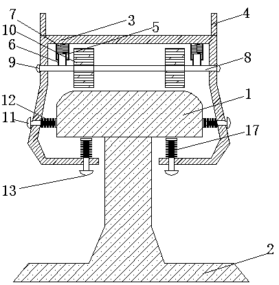
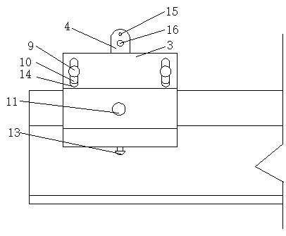
[0019] An embodiment of the present invention provides a rail cutting machine damping seat device, such as Figure 1-2 As shown, the guide rail 1 is included, the bottom of the guide rail 1 is fixedly connected with the base 2, the outside of the guide rail 1 and above the base 2 is sleeved with a shock absorber 3, and the top of the shock absorber 3 is fixedly connected with two external devices 4, A first small hole 15 and a second small hole 16 are opened o...


PUM


Abstract

The invention provides a shock-absorbing seat device of a steel rail cutter, and relates to the industrial field. The shock-absorbing seat device of the steel rail cutter comprises a guiding rail of which the bottoms is fixedly connected to a base, and a shock-absorbing seat is sheathed at the outside of the guiding rail and located above the base; the top of the shock-absorbing seat is fixedly connected to two external devices, and the sides, far away from each other, of the two external devices are both provided with first small holes and second small holes; and the first small holes are located above the second small holes. The inner wall top of the shock-absorbing seat is fixedly connected to two groups of damping sleeves, and each group includes two damping sleeves; the interiors of the two groups of the damping sleeves are fixedly connected to first damping springs, and the bottoms of the damping springs and the bottoms of the damping sleeves are connected to first damping rods by insertion. The shock-absorbing seat device of the steel rail cutter has the advantages that the continuous cutting is convenient, and the use efficiency of the cutter is improved; both ends of the damping rods are provided with stop blocks, in favor of spring damping in the shock-absorbing seat as well as reduction of vibration.

Description

technical field [0001] The invention relates to the field of industrial technology, in particular to a damping seat device for a rail cutting machine. Background technique [0002] Rail transport is a mode of land transport in which trains are guided on two parallel rigid rails. Railway transportation is one of the most effective known land transportation methods. Railway transportation requires frequent repairs and maintenance of railway facilities. At present, rail cutting machines can be divided into internal combustion rail cutting machines and electric rail cutting machines according to the power form. , The internal combustion rail cutting machine is mainly powered by a gasoline engine, suitable for use in the field without power supply. In engineering applications, the rail cutting machine needs to move laterally and the stone road paved by the rail is not smooth, which is not conducive to the walking of the cutting machine. The cutting process takes a long time, and...

Claims


Application Information

Patent Timeline
Patent Type & Authority Patents(China)
IPC IPC(8): B23Q11/00
CPCB23Q11/0032
Inventor 朱德金
Owner YANCHENG AIFEIER MUSHROOM EQUIP TECH
Learn More