
Cutting apparatus and printer

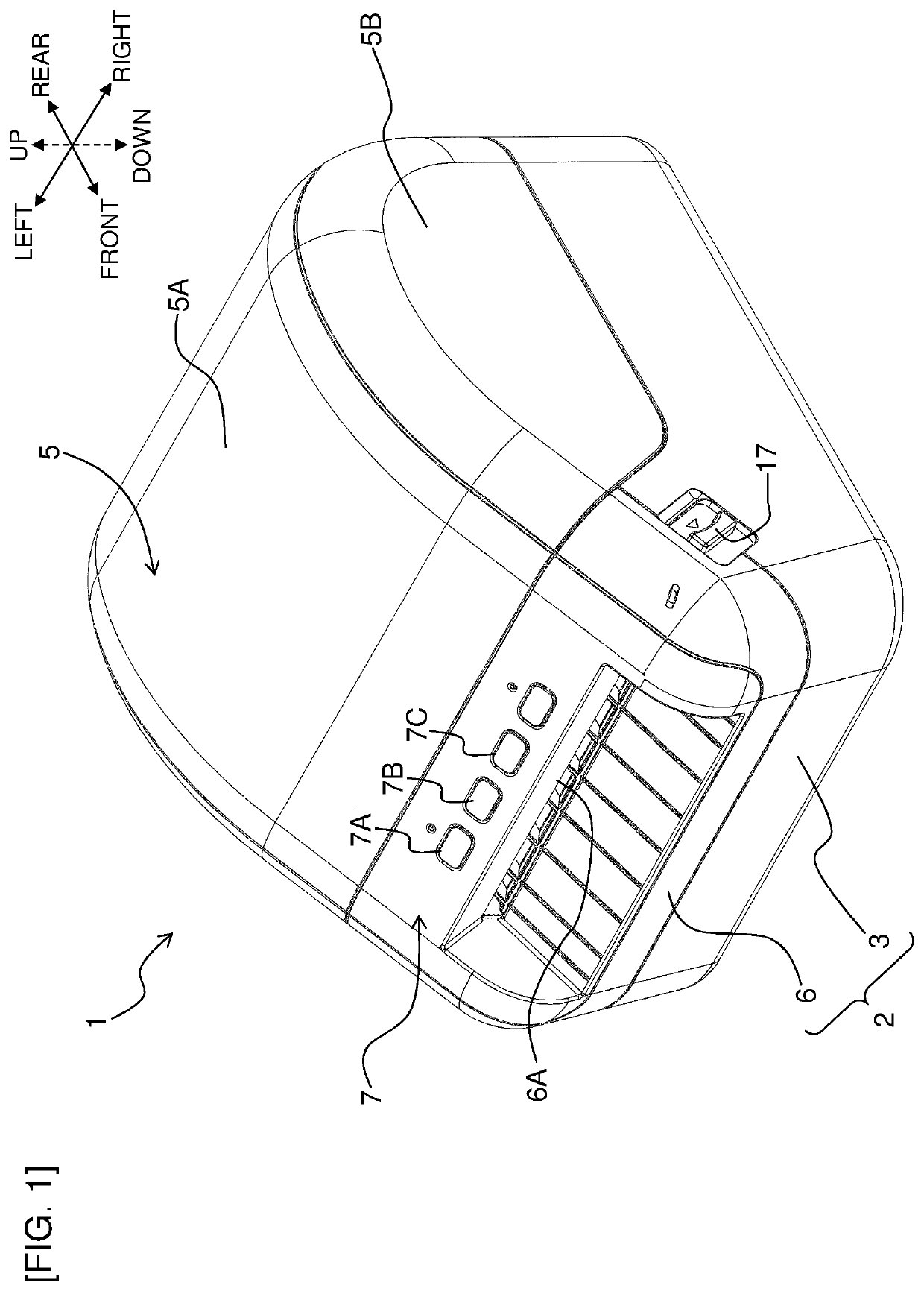
a cutting machine and printer technology, applied in the field of cutting machines, to achieve the effect of significant increase in the amount of elastic deformation in the upwardly bending form

Active Publication Date: 2021-01-05
BROTHER KOGYO KK
View PDF6 Cites 0 Cited by
  • Summary
  • Abstract
  • Description
  • Claims
  • Application Information

AI Technical Summary

Benefits of technology

[0005]An object of the present disclosure is to provide a cutting apparatus and a printer capable of reliably discharging a cut print-receiving medium.
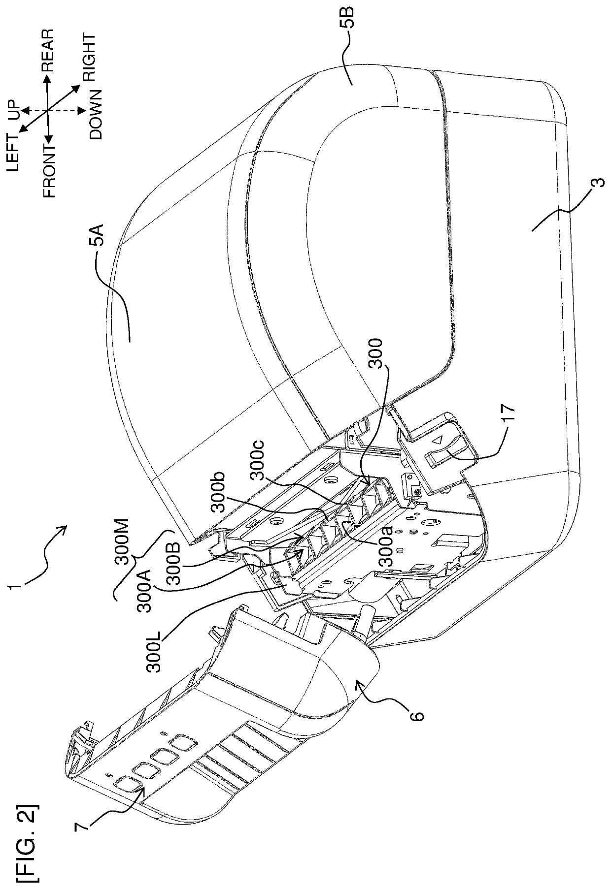
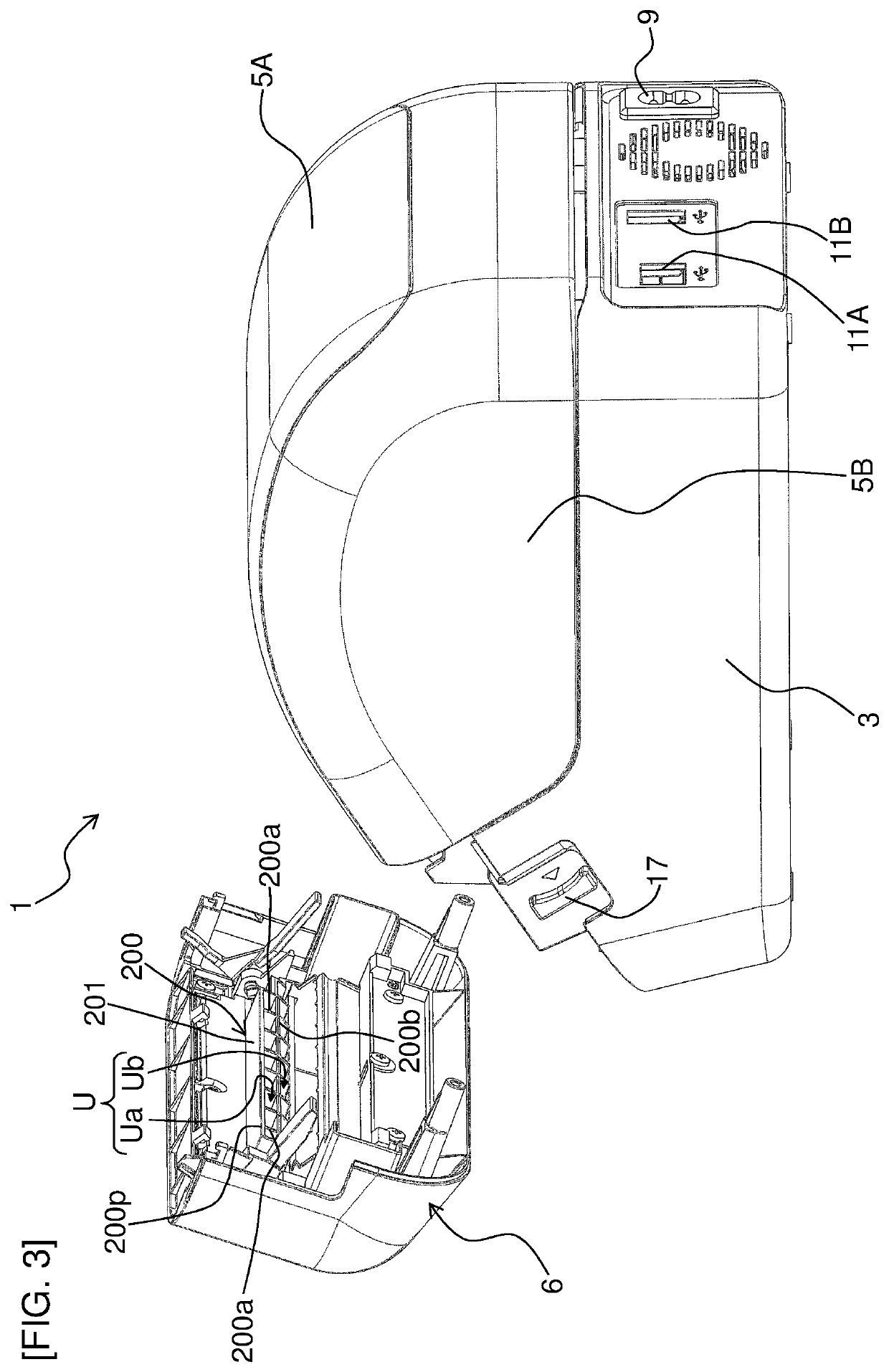
[0008]The upper guide part includes the contact part at a position separated from the first blade edge of the fixed blade by the first distance in the transport direction and by the second distance in the upper direction. The lower guide part includes the guide surface inclined downward at a predetermined angle toward the downstream side in the transport direction at an interval of the third distance from the contact part. The print-receiving medium usually has a certain degree of rigidity (so-called stiffness), and therefore, when being cut as the movable blades ascends, the medium comes into point contact or line contact from below with the contact part so that the contact portion is restrained from further moving upward, and the medium elastically deforms such that the end portion on the cut side (the upstream side in the transport direction) gradually bends upward. Furthermore, the print-receiving medium comes into contact from above with the guide surface so that the contact portion is thereby restrained from further moving downward, and therefore, an amount of the elastic deformation in the upwardly-bending form significantly increases as the cutting progresses.
[0009]As a result, when the print-receiving medium is completely cut, and the elastic deformation rapidly returns to the original state, the end portion of the cut print-receiving medium on the cut side (the upstream side in the transport direction) presses the side surface of the movable blade on the upstream side in the transport direction, and the cut print-receiving medium is discharged due to the reaction force in a pop-out manner from the discharging exit. As a result, according to this embodiment, the cut print-receiving medium can reliably be discharged from the discharging exit without staying in the guide part or the discharging exit.

Problems solved by technology

However, when the length of the cut print-receiving medium is short, the medium may stay in the discharge path part without being discharged.

Method used


Image

  • Cutting apparatus and printer
  • Cutting apparatus and printer
  • Cutting apparatus and printer

Examples


embodiment

Advantages of Embodiment

[0114]As described above, in this embodiment, the scraping-off mechanism is disposed in proximity to the movable blade 47 separately from the movable blade 47 and the fixed blade 46. As a result, the adhesive having adhered to the movable blade 47 is brought into contact therewith and scraped off when the movable blade 47 moves from the lower side to the upper side. Consequently, the adhesive adhering to the movable blade 47 can be reduced by a simple and inexpensive configuration without disposing multiple tapered through-holes in the fixed blade and the movable blade as in the conventional case.

[0115]Particularly in this embodiment, the substantially flat plate-like extension part 310 is disposed on the front side of the movable blade 47 to face the movable blade 47, and the slope part 320 is formed on the lower end portion of the extension part 310 and is inclined toward the movable blade 47 while extending to the lower side. As a result, when the movable ...


PUM

PropertyMeasurementUnit
distanceaaaaaaaaaa
distanceaaaaaaaaaa
angleaaaaaaaaaa

Abstract

The disclosure discloses a cutting apparatus including a movable blade and a guide device. The movable blade is configured to move along a sliding direction to a cutting position. The guide device includes an upper guide part including a contact part and a lower guide part including at least one guide surface. The contact part is disposed at a position separated from a first blade edge of the fixed blade by a first distance in the transport direction and by a second distance in an upper direction. The at least one guide surface that inclines in an inclination direction in which the at least one guide surface inclines downward at a predetermined angle toward a downstream in the transport direction and is disposed to have an interval of a third distance against the contact part in a direction orthogonal to the inclination direction.

Description

CROSS-REFERENCE TO RELATED APPLICATION[0001]The present application claims priority from Japanese Patent Application No. 2017-141376, which was filed on Jul. 20, 2017, the disclosure of which is incorporated herein by reference in its entirety.BACKGROUNDField[0002]The present disclosure relates to a cutting apparatus cutting a print-receiving medium including an adhesive layer, and a printer including the cutting apparatus.Description of the Related Art[0003]A printer (tape printer) is known that includes a cutting apparatus (cutter unit) cutting a print-receiving medium (roll sheet) including an adhesive layer. In this printer according to the prior art, the print-receiving medium cut by a movable blade and a fixed blade of the cutting apparatus is finally discharged through a discharge path part.[0004]In the printer of the prior art, the discharge path part includes a projecting part, a regulating member, a roll-sheet receiving part, a rib, etc., and even if the cut print-receivin...

Claims


Application Information

Patent Timeline
Patent Type & Authority Patents(United States)
IPC IPC(8): B65H35/00B41J11/70B41J3/407
CPCB41J11/703B41J3/4075B65H35/002B65H35/006B65H35/0086B65H2301/515326B65H2701/19404B65H2801/12
Inventor OSUKA, MISATOTAKAHASHI, RYOYAJO, HIDENORIIWAMOTO, MASASHI
Owner BROTHER KOGYO KK
Learn More