
Flat tire sealant storage container and flat tire repair device

a flat tire and storage container technology, applied in the field of flat tire sealant storage containers and flat tire repair devices, can solve problems such as inability to stably place, and achieve the effects of stable and reliable placement, reliable discharge, and simple configuration

Inactive Publication Date: 2013-08-27
THE YOKOHAMA RUBBER CO LTD
View PDF13 Cites 19 Cited by
  • Summary
  • Abstract
  • Description
  • Claims
  • Application Information

AI Technical Summary

Benefits of technology

[0007]An object of the present invention is to provide a flat tire sealant storage container which solves the above problem and which is formed in a simple configuration enabling the container to be stably secured even on an inclined or rough road surface, and a flat tire repair device having the container.
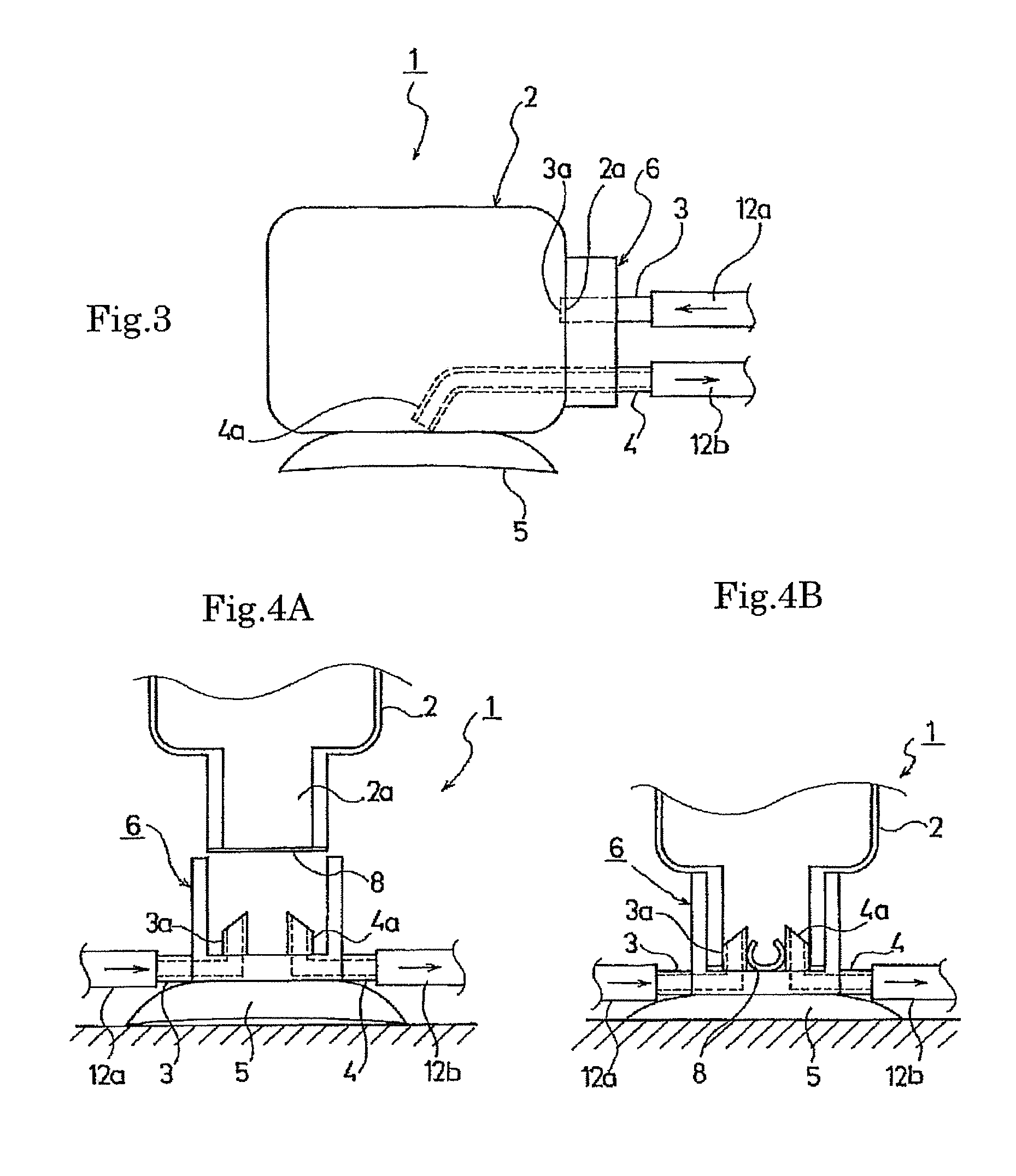
[0026]In the present invention, the flat tire sealant storage container comprises an air inflow section for injecting compressed air under pressure into a container filled with a flat tire sealant and a sealant discharge section for discharging the flat tire sealant under pressure to the outside of the container. The flat tire sealant storage container further comprises a fixing device which is provided on the outer surface of the container and which is attachable to and detachable from an external object, and the container is secured to the external object by means of the fixing device. Accordingly, the flat tire sealant storage container enables the container to be stably and reliably secured by a simple configuration even on an inclined or rough road surface. Moreover, when the container is secured to the external object by means of the fixing device, the inlet of the sealant discharge section is positioned at the inner lower part of the container, thereby enabling the flat tire sealant to be reliably discharged.

Problems solved by technology

On an inclined road surface, a rough road and the like, however, the legs have a problem that the container may turn over, for example, and thus cannot be stably placed.

Method used


Image

  • Flat tire sealant storage container and flat tire repair device
  • Flat tire sealant storage container and flat tire repair device
  • Flat tire sealant storage container and flat tire repair device

Examples


Embodiment Construction

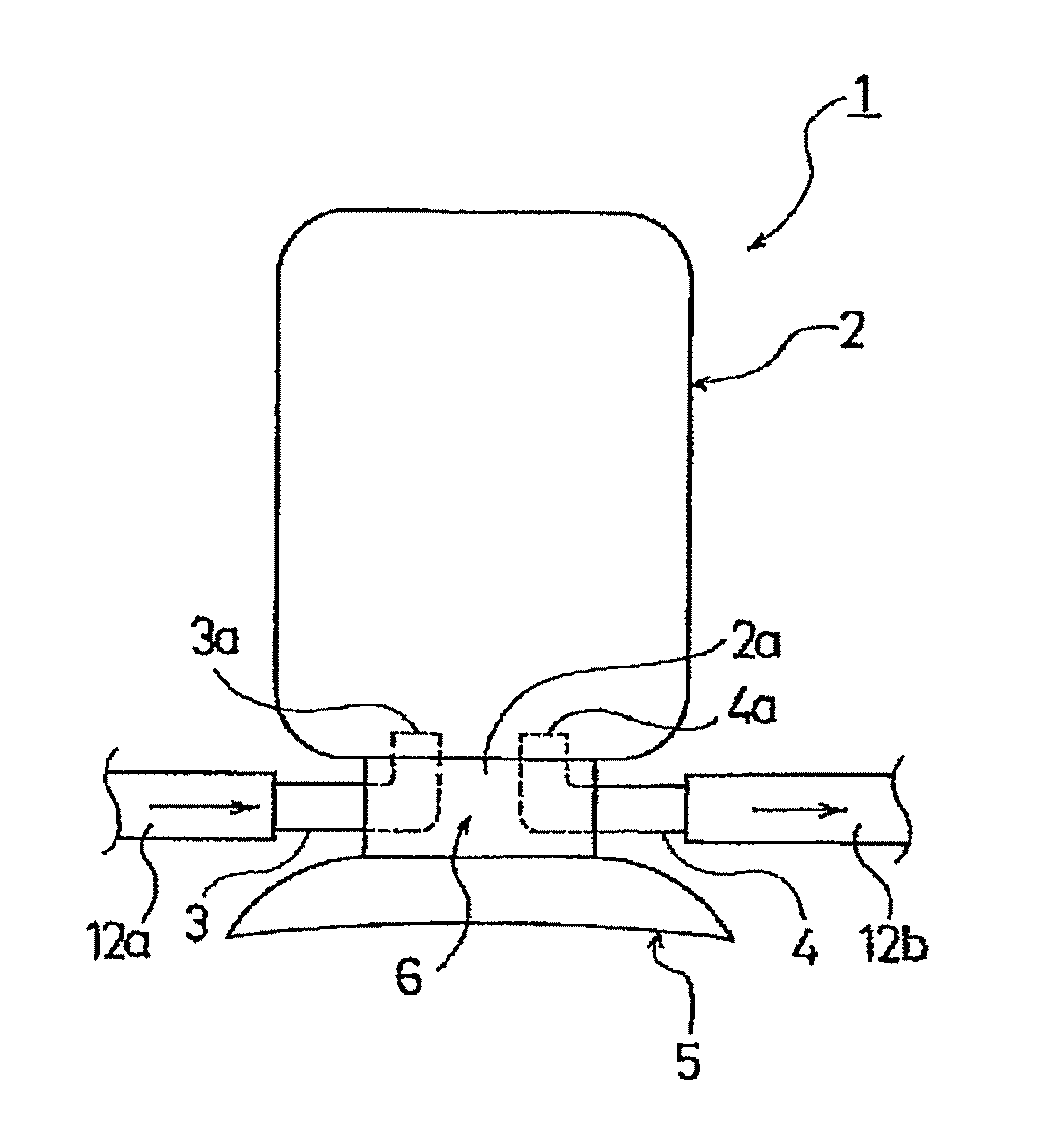
[0045]FIG. 1 is a schematic view showing a flat tire sealant storage container according to an embodiment of the present invention.

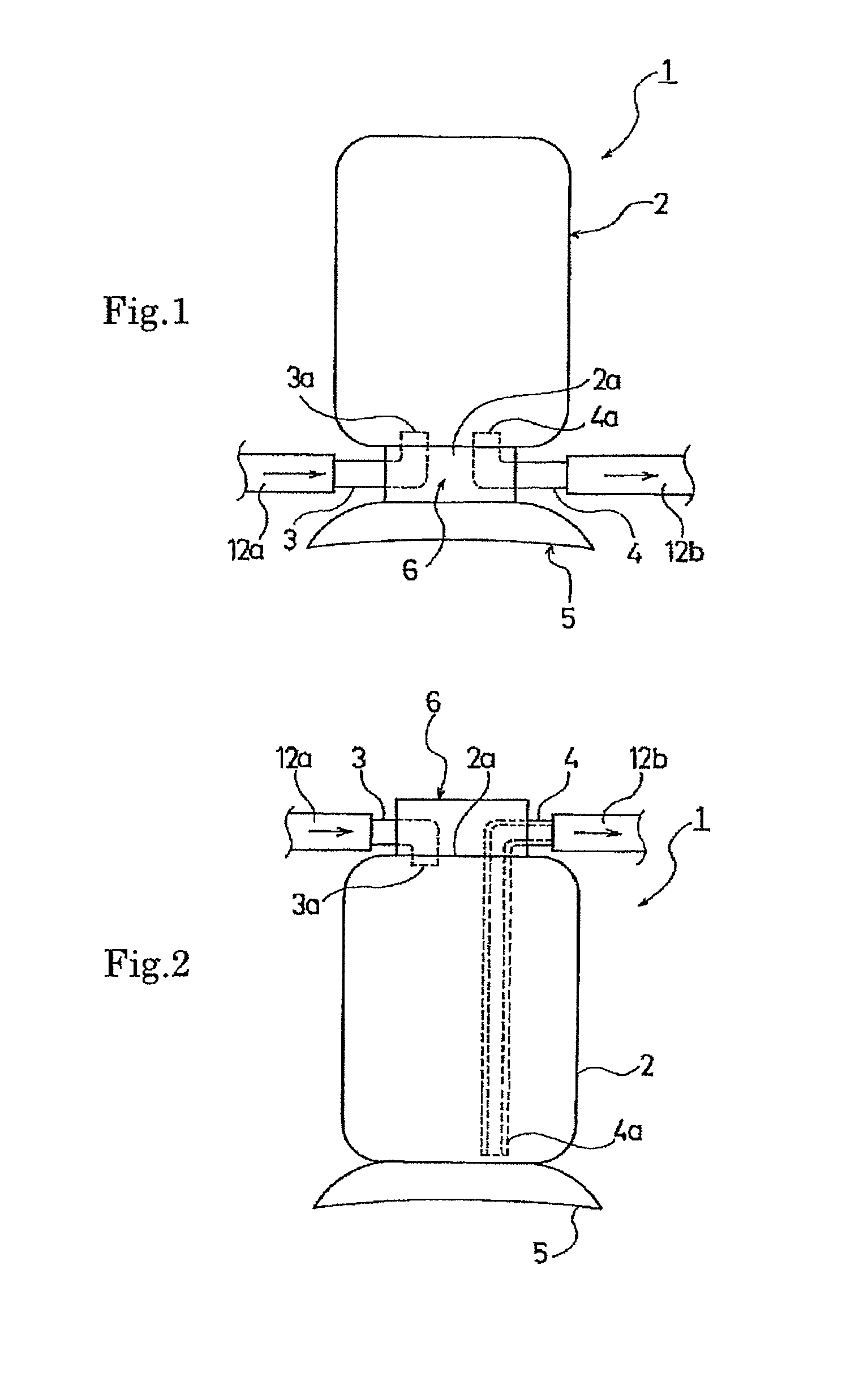
[0046]A container 1 includes a main body 2 that at least partially defines an interior space that stores a flat tire sealant. The main body 2 has an opening 2a provided in its lower side relative to when the container 1 is in a usage state as seen in FIG. 12. The main body 2 includes a cap 6 detachably secured to a vessel portion of the main body 2. The cap 6 is attached to the vessel portion of the main body 2 to cover an opening 2a provided in a lower side of the vessel portion of the main body 2. In the opening 2a having the cap 6 attached thereto, there are provided an air inflow pipe or section 3 and a sealant discharge pipe or section 4. The air inflow pipe or section 3 is configured to be connected to a compressor C (FIG. 12) through a hose 12a. As seen in FIG. 12, the sealant discharge pipe or section 4 is configured to be connected to flat tire ...


PUM

PropertyMeasurementUnit
weightaaaaaaaaaa
areaaaaaaaaaaa
pressureaaaaaaaaaa

Abstract

A flat tire sealant storage container is provided for a flat tire repair device in a formed in a simple configuration which enables the container to be stably secured. The flat tire sealant storage container includes an air inflow pipe for injecting compressed air under pressure into the container filled with a flat tire sealant and a sealant outlet discharge pipe for discharging the flat tire sealant under pressure to the outside of the container. The flat tire sealant storage container further includes an attachable and detachable fixing device formed on the outer surface of the container. When the container is secured to an external object by the fixing device, the inlet of the sealant outlet discharge pipe is positioned at the inner lower part of the container.

Description

CROSS-REFERENCE TO RELATED APPLICATIONS[0001]This U.S. National stage application claims priority under 35 U.S.C. §119(a) to Japanese Patent Application No. 2008-269959, filed in Japan on Oct. 20, 2008 and Japanese Patent Application No. 2008-265758, filed in Japan on Nov. 19, 2008, the entire contents of which are hereby incorporated herein by reference.TECHNICAL FIELD[0002]The present invention relates to a flat tire sealant storage container and a flat tire repair device. More specifically, the present invention relates to a flat tire sealant storage container formed in a simple configuration enabling the container to be stably secured and a flat tire repair device having the container.BACKGROUND ART[0003]There has recently been in widespread use a flat tire repair kit which, when a pneumatic tire (hereinafter simply called the “tire”) goes flat, injects a flat tire sealant into the flat tire, fills the flat tire sealant into a puncture hole, and then increases the pressure in th...

Claims


Application Information

Patent Timeline
Patent Type & Authority Patents(United States)
IPC IPC(8): B65B31/00
CPCB29C73/166B29L2030/00
Inventor KANENARI, DAISUKESEKIGUCHI, TAKUMI
Owner THE YOKOHAMA RUBBER CO LTD
Learn More