
Lens driving device, camera device, and electronic apparatus

a technology of lens holder and lens holder, which is applied in the direction of mountings, optics, instruments, etc., can solve the problems of unstable and achieve the effect of increasing reducing the elastic deformation amount, and stable posture of the lens holder

Active Publication Date: 2019-07-09
NEW SHICOH MOTOR CO LTD
View PDF14 Cites 0 Cited by
  • Summary
  • Abstract
  • Description
  • Claims
  • Application Information

AI Technical Summary

Benefits of technology

[0006]The present invention aims to solve the problem of the prior art, and to provide a lens driving device, a camera device, and an electronic apparatus which are able to stabilize the posture of the lens holder.
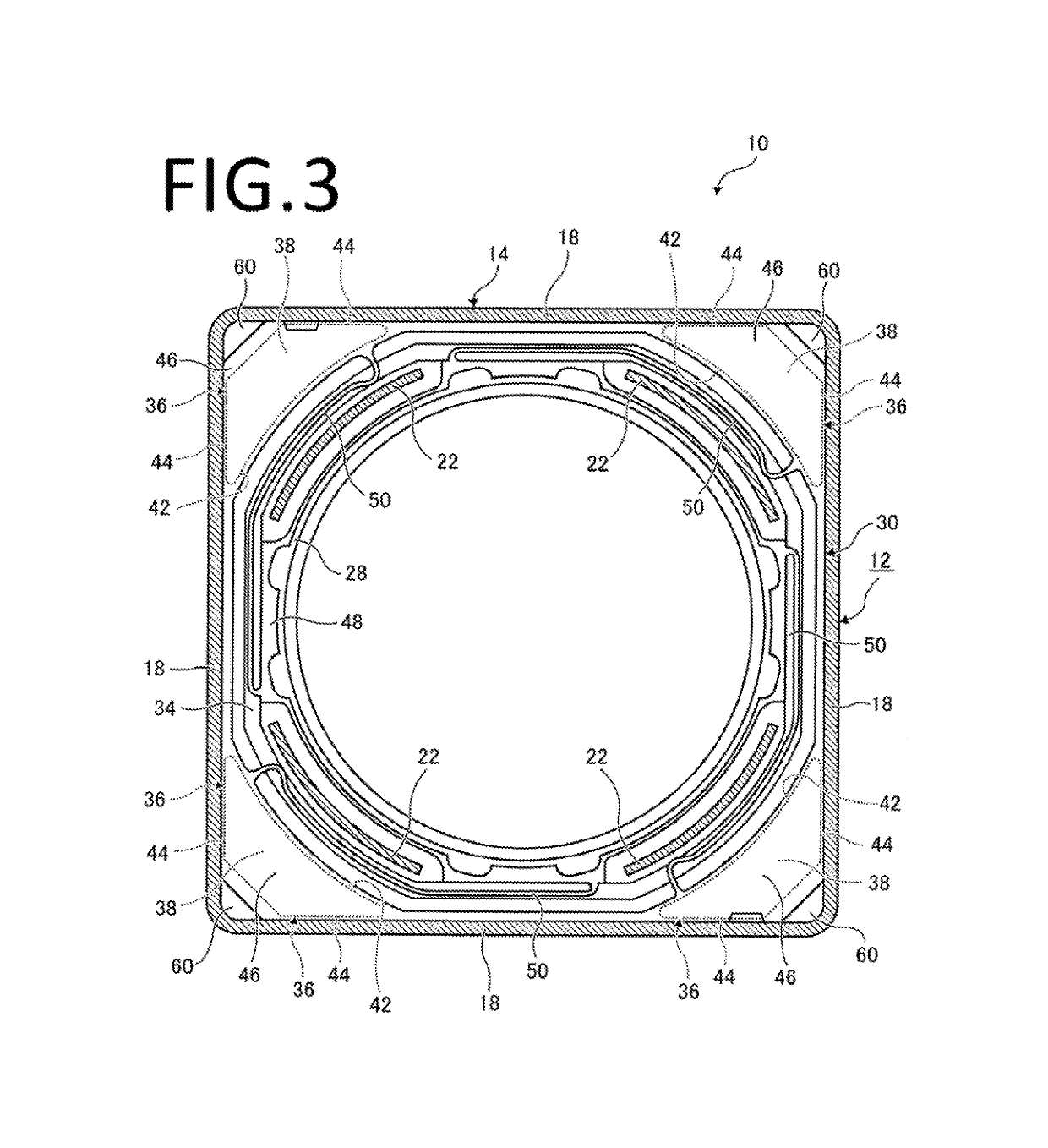
[0015]According to the present invention, when the lens holder moves along the optical axis direction, the elastic arm of one of the first spring member and the second spring member increases its elastic deformation amount while the elastic arm of the other one of the first spring member and the second spring member decreases its elastic deformation amount. In this moment, the elastic arm of one of the first spring member and the second spring member rotates the lens holder so that the second connecting point moves close to the first connecting point in a circumferential direction when viewing from one side of the optical axis direction. Further, the elastic arm of other one of the first spring member and the second spring member rotates the lens holder so that the second connecting point moves apart from the first connecting point in the circumferential direction. Since an offset direction of the second connecting point to the first connecting point in the first spring member and the offset direction of the second connecting points to the first connecting points in the second spring member are set in the opposite circumferential direction to each other when viewing from one side of the optical axis direction, thus the leas holder rotates into the same circumferential direction at the positions of the first spring member and the second spring member. Therefore, since there is less possibility that the lens holder tilts deviating from the optical axis direction, the posture of the lens holder can be stable.

Problems solved by technology

It raises a problem of making the posture of the lens holder be unstable.

Method used


Image

  • Lens driving device, camera device, and electronic apparatus
  • Lens driving device, camera device, and electronic apparatus
  • Lens driving device, camera device, and electronic apparatus

Examples


first embodiment

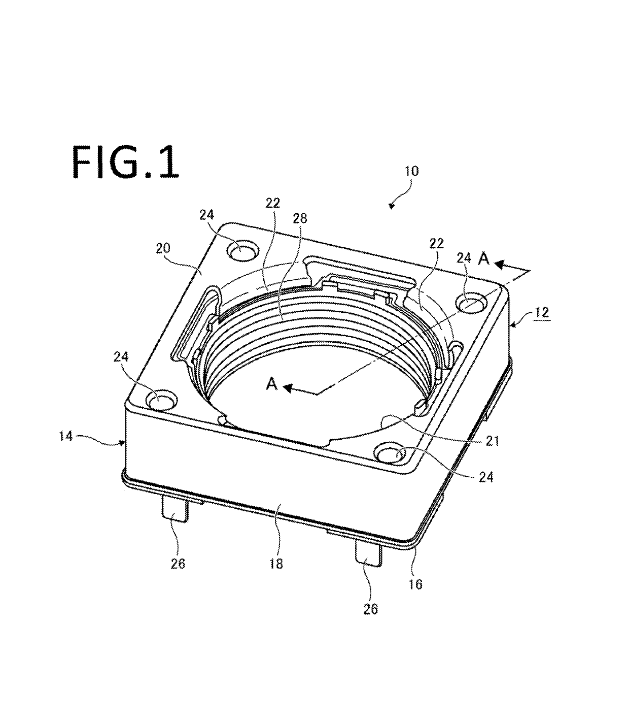
[0024]FIG. 1 is a perspective view of the lens driving device 10 according to the present invention. The lens driving device 10 has a housing 12 formed as a rectangular parallelepiped shape. The housing 12 includes a yoke 14 and a base 16.

[0025]The yoke 14 is a rectangular parallelepiped shape and has an outer wall 18 which encloses four sides thereof and a top wall 20 which is provided on the top thereof. The top wall 20 is formed with a first hole 21 which has a substantially circular shape and through which first hole 21 the light passes. The first hole 21 is formed with internal walls 22 projected downward from the inner four regions thereof which are near the four corners of the yoke 14. The top wall 20 is formed with recessed parts 24 which are recessed downward at the four corners of the top wall 20.

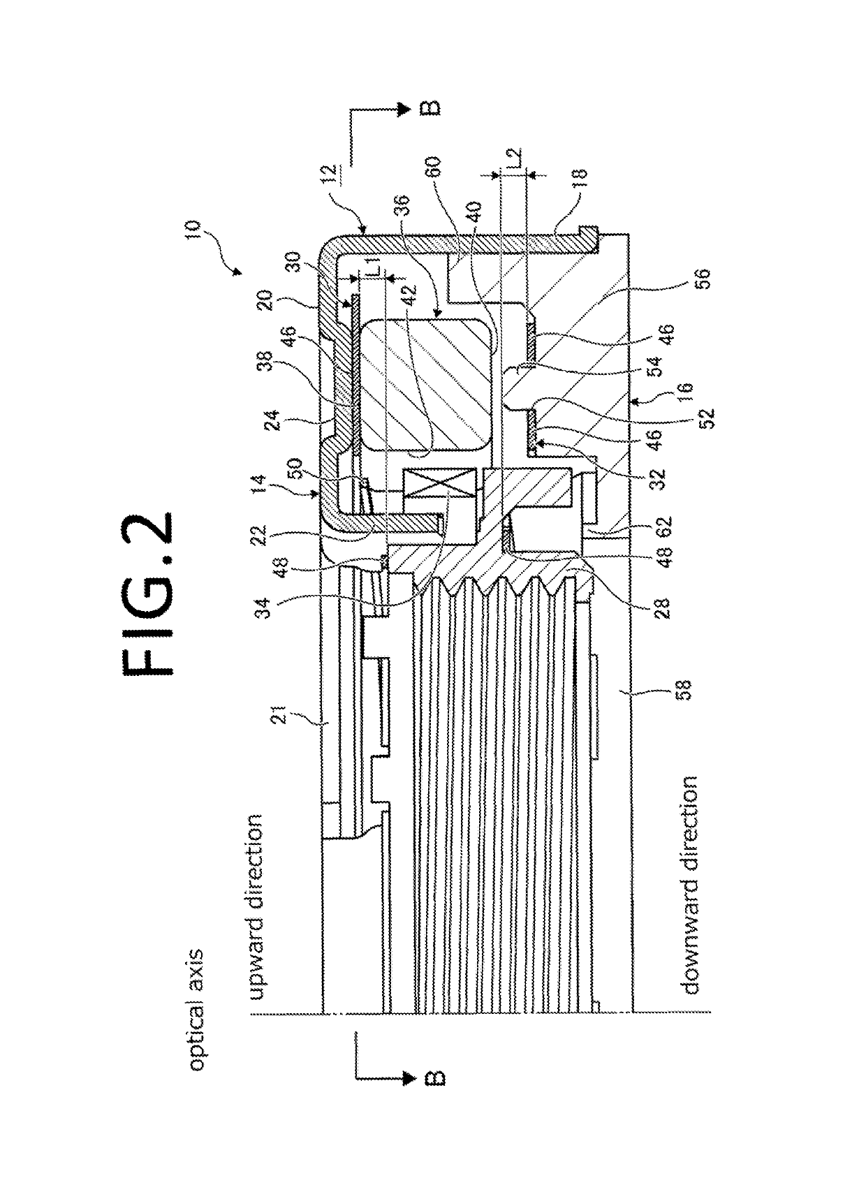
[0026]It would be noted throughout this explanation that the direction toward upper side in the drawing of FIG. 1 is referred to as an upward direction while the direction toward ...

second embodiment

[0048]the present invention will be explained hereinafter.

[0049]In the aforementioned first embodiment, the lens holder side fixing members 48, 48 are arranged within the width between the housing side fixing members 46, 46 in the optical axis direction. On the other hand, in the second embodiment, the lens holder side fixing members 48, 48 are arranged outside of the width between the housing side fixing members 46, 46 in the optical axis direction. That is to say, in the initial state, the lens holder side fixing member 48 of the first spring member 30 is positioned at a height higher the height of the housing side fixing member 46 thereof while the lens holder side fixing members 48 of the second spring member 32 are positioned at a height lower than the height of the housing side fixing members 46 thereof.

[0050]When the lens holder 28 moves upward from the such initial state, although the elastic deformation amount of the elastic arms 50 of the first spring member 30 increases h...


PUM


Abstract

The lens driving device includes: a housing, a lens holder, and first and second spring members that support the lens holder at both sides of the lens holder in an optical axis direction; wherein the first and second spring member each has a housing side fixing member fixed to the housing, a lens holder side fixing member fixed to the lens holder, and elastic arms therebetween. A first connecting point connecting the elastic arm with the housing side fixing member and a second connecting point connecting the elastic arm with the lens holder side fixing member are arranged offset to each other in a circumferential direction and an offset direction of the second connecting point to the first connecting point in the first spring member and an offset direction of the second connecting point to the first connecting point in the second spring member are opposite.

Description

CROSS REFERENCE TO RELATED APPLICATIONS[0001]This application claims priority to Japanese Patent Application No. 2015-086723 filed on Apr. 21, 2015; and the entire contents of which are incorporated by reference herein.TECHNICAL FIELD[0002]This invention relates to a lens driving device, a camera device, and an electronic apparatus.BACKGROUND ART[0003]Electronic apparatuses such as cellular phones and smart phones are equipped with a miniaturized camera. The miniaturized camera of this type is an automatic focusing type. The miniaturized camera of this automatic focusing type includes a lens driving device for actuating the lens to move.[0004]The Publication of Japanese Utility Model Registration No. 3186519 discloses a lens driving device in which a lens holder for supporting a lens is provided within a frame, the lens holder is supported by spring members at the both sides thereof optical axis direction so that the lens holder can move toward both directions along the optical axis...

Claims


Application Information

Patent Timeline
Patent Type & Authority Patents(United States)
IPC IPC(8): G02B7/08
CPCG02B7/08
Inventor SEKIGUCHI, NAOKI
Owner NEW SHICOH MOTOR CO LTD
Learn More