
Novel micro-tillage machine for agricultural machine

A technology of agricultural machinery and micro tillage machine, which is applied in the field of new type of micro tillage machine for agricultural machinery, which can solve the problems of device damage, inability to flexibly adjust the distance between the tiller and the ground, strong vibration, etc., to achieve reduced vibration and good cushioning Function, the effect of increasing the contact area

Active Publication Date: 2017-10-20
池州市勇攀智岩机电有限公司
View PDF7 Cites 1 Cited by
  • Summary
  • Abstract
  • Description
  • Claims
  • Application Information

AI Technical Summary

Problems solved by technology

[0003] The purpose of the present invention is to provide a new type of micro-tiller for agricultural machinery, to solve the problem that the micro-tiller for agricultural machinery on the market can not flexibly adjust the distance between the tiller and the ground, and the device is in the process of moving. There will be strong vibration, which is easy to cause damage to the device

Method used


Image

  • Novel micro-tillage machine for agricultural machine
  • Novel micro-tillage machine for agricultural machine
  • Novel micro-tillage machine for agricultural machine

Examples


Embodiment Construction

[0023] The technical solutions in the embodiments of the present invention will be clearly and completely described below in conjunction with the accompanying drawings in the embodiments of the present invention. Obviously, the described embodiments are only a part of the embodiments of the present invention, rather than all the embodiments. Based on the embodiments of the present invention, all other embodiments obtained by those of ordinary skill in the art without creative work shall fall within the protection scope of the present invention.

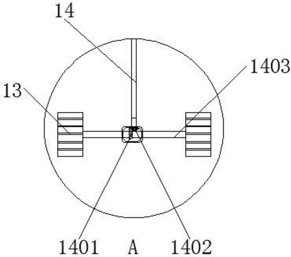
[0024] See Figure 1-4 , The present invention provides a technical solution: a new type of micro-tiller for agricultural machinery, including a base 1, a diesel engine 2, a transverse transmission rod 3, a reducer 4, a first transmission belt 5, a transmission shaft 6, a bearing 7, and a mounting plate 8. Rotating wheel 9, adjusting mechanism 10, tiller 11, driving wheel 12, second transmission belt 13, transmission mechanism 14, buffer...


PUM


Abstract

The invention discloses a novel micro-tillage machine for an agricultural machine. The novel micro-tillage machine comprises an engine base and a bearing, wherein a diesel engine is mounted at the upper end of the engine base; a speed reducer is mounted at the right side of the diesel engine; a transverse transmission rod is mounted between the diesel engine and the speed reducer; a mounting disc is fixed at the outer side of a rotating wheel; the outer side of the mounting disc is connected with a rotary blade through a regulating mechanism; a caterpillar track is arranged below the engine base; a driving wheel and a driven wheel are mounted at left and right sides in the caterpillar track respectively; the left side of the driving wheel is connected with a transmission mechanism through a second transmission belt; the upper end of the transmission mechanism is connected with the diesel engine; the caterpillar track is internally provided with a buffering mechanism; the buffering mechanism is located between the driven wheel and the driving wheel; and a handle is fixed at the left side of the engine base. The novel micro-tillage machine for the agricultural machine, disclosed by the invention, is provided with the regulating mechanism and the distance of the rotary blade can be conveniently regulated; and the distance, exceeding the rotating wheel, of the rotary blade can be conveniently controlled so that the distance, entering the ground, of the machine can be regulated.

Description

Technical field [0001] The invention relates to the technical field of agricultural machinery, in particular to a new type of micro-tiller for agricultural machinery. Background technique [0002] The micro-tiller for agricultural machinery is a kind of mechanical equipment that can facilitate people's agricultural production. It has the characteristics of light weight, small size, and simple structure. Therefore, it is widely used in plain, mountainous, hilly and other farming. Powered by small diesel engines, with the development of science and technology, the new agricultural machinery micro-tillers have developed to a great extent, and their types and numbers are also increasing day by day. Although there are many types and quantities of tillers for agricultural machinery on the market at present, most of the tillers for agricultural machinery cannot flexibly adjust the distance between the tiller and the ground. At the same time, the device will produce strong vibration duri...

Claims


Application Information

Patent Timeline
Patent Type & Authority Applications(China)
IPC IPC(8): A01B33/02A01B33/08A01B33/10A01B33/12
CPCA01B33/021A01B33/028A01B33/08A01B33/087A01B33/103A01B33/12
Inventor 沈抗勇宗寒胡鉴涛
Owner 池州市勇攀智岩机电有限公司
Learn More