A method to reduce the influence of laser random frequency offset in flexible grid elastic optical network

A technology of elastic optical network and flexible grid, applied in digital transmission system, electrical components, electromagnetic wave transmission system, etc., can solve problems such as waste of spectrum resources and inflexible frequency grid allocation

Inactive Publication Date: 2019-05-28
UNIV OF ELECTRONICS SCI & TECH OF CHINA
View PDF3 Cites 0 Cited by
  • Summary
  • Abstract
  • Description
  • Claims
  • Application Information

AI Technical Summary

Problems solved by technology

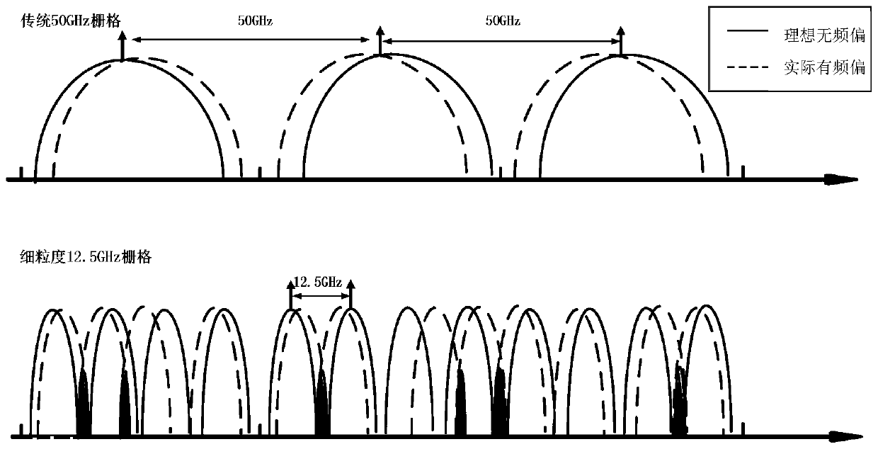
There are mainly two traditional frequency grid allocation methods: one allocation method is to allocate as many continuous frequency grids as possible for the services corresponding to the same source and sink nodes, and the allocated multiple continuous frequency grids are regarded as a super channel Switching and routing are performed, so the random frequency offset will only affect the grid at the edge, and the signal is less affected by the random frequency offset, but it is easy to generate spectrum fragments in this spectrum resource allocation, resulting in waste of spectrum resources and frequency grid allocation. Inflexible; another division method is to allocate independent and fine-grained frequency grids, that is, first divide the fixed frequency grid of 50 GHz into multiple fine-grained frequency grids, and support the transmission of fine-grained sub-wavelength signals At the same time, it can realize the change of service modulation format, better realize service matching and flexible transmission, and improve the overall performance index of the network while improving the spectrum utilization rate, so as to meet the transmission requirements of large capacity, high efficiency and low energy consumption in the future, but The random frequency offset of the laser has a significant impact on this independent, fine-grained signal

Method used


Image

  • A method to reduce the influence of laser random frequency offset in flexible grid elastic optical network
  • A method to reduce the influence of laser random frequency offset in flexible grid elastic optical network
  • A method to reduce the influence of laser random frequency offset in flexible grid elastic optical network

Examples


Embodiment

[0038] Figure 4 It is a flow chart of the first embodiment of the method for reducing the influence of random frequency offset of lasers in the flexible grid elastic optical network of the present invention. Such as Figure 4 As shown, the specific steps of the method for reducing the influence of laser random frequency offset in the flexible grid elastic optical network of the present invention include:

[0039] S401: frequency raster division:

[0040] The fixed frequency grid is divided into several fine-grained frequency grids to obtain the initial reuse frequency of each frequency grid. The specific division parameter, namely the number of fine-grained frequency grids, is determined according to actual needs.

[0041] S402: Routing and wavelength allocation:

[0042] According to the source and sink nodes of the business, the traffic demand of the business and the current network resources, the routing and wavelength allocation are carried out for the business. The fr...


PUM


Abstract

The invention discloses a method for reducing the influence of random frequency offset of lasers in a flexible grid elastic optical network. Firstly, the fixed frequency grid is divided into several fine-grained frequency grids, and then according to the source and sink nodes of the business and the business flow requirements As well as the current network resources, for routing and wavelength allocation for services, it is necessary to ensure that the frequency grids allocated by each source and sink node are continuous during allocation, and then compress the frequency interval of each group of continuous frequency grids, and the frequency interval There are two methods of compression, one is compression without spectral overlap, which can be received and restored by conventional methods, and the other is compression with spectral overlap, which is restored by a butterfly equalizer. The invention compresses the frequency interval of the continuous frequency grid, reduces the mutual influence between random frequency offsets of lasers of different source and sink nodes, and improves the transmission performance of the flexible grid elastic optical network.

Description

technical field [0001] The invention belongs to the technical field of flexible grid elastic optical network, and more specifically relates to a method for reducing the influence of random frequency deviation of lasers in flexible grid elastic optical network. Background technique [0002] With the development of broadband services, such as data center services and big data services, optical networks are required to have the characteristics of ultra-large capacity, dynamic flexibility, and service self-adaptation. The traditional WDM (Wavelength Division Multiplexing, wavelength division multiplexing) system is limited by the fixed grid, which makes the network optical wavelength utilization rate low, the optical channel lacks flexibility, and the optical signal is not flexible enough, which cannot meet the future service-oriented network development needs. In order to overcome the above problems, it can be considered to further divide the spectrum bandwidth of the fixed gri...

Claims


Application Information

Patent Timeline
Patent Type & Authority Patents(China)
IPC IPC(8): H04B10/516H04L27/00
CPCH04B10/5165H04L27/0014H04L2027/0026
Inventor 赵燕许渤邱昆
Owner UNIV OF ELECTRONICS SCI & TECH OF CHINA
Why Eureka
Try Eureka