
Thermal radiation coating composition for automobile lamp and preparation method of thermal radiation coating composition

A technology of radiation heat dissipation and composition, applied in the direction of fireproof coatings, coatings, etc., can solve the problems of anti-fog failure, flowing appearance, increasing the load of car lights, etc., and achieve the effects of low volatility, low environmental pollution, and easy coating

Inactive Publication Date: 2017-10-17
HASCO VISION TECHNOLOGY CO LTD
View PDF3 Cites 1 Cited by
  • Summary
  • Abstract
  • Description
  • Claims
  • Application Information

AI Technical Summary

Problems solved by technology

Anti-fog coating is currently the most commonly used solution, but there are risks of anti-fog failure and appearance flow; the use of desiccant can only reduce the air humidity in the iso-cavity to a certain extent, and cannot fundamentally determine the formation of fog in the optical mirror. Increased the load of the car lights; the improvement of the structure of the lamps is currently mainly playing an auxiliary role, and the shape of the car lights determines that local blind spots cannot be avoided

Method used


Image

  • Thermal radiation coating composition for automobile lamp and preparation method of thermal radiation coating composition
  • Thermal radiation coating composition for automobile lamp and preparation method of thermal radiation coating composition
  • Thermal radiation coating composition for automobile lamp and preparation method of thermal radiation coating composition

Examples


Embodiment 1

[0036] 12 parts of multi-armed carbon nanotubes, 15 parts of montmorillonite with an average particle diameter of 75nm, 20 parts of spinel, 8 parts of surfactant (wetting and dispersing agent: defoamer: emulsifier: leveling agent=6:1.5 :2:0.5), 30 parts of deionized water, 15 parts of other additives (stabilizer:plasticizer=8:7). The average thickness of the coating after film formation is 10um, the temperature resistance is above 200°C, and the temperature drop is 20%. It can pass the PV1200 (20) cycle test.

Embodiment 2

[0038] 15 parts of multi-armed carbon nanotubes, 20 parts of illite with an average particle diameter of 75nm, 15 parts of spinel, 5 parts of surfactant (wetting and dispersing agent: defoamer: emulsifier=6:1.5:2.5), solvent 35 parts (deionized water: absolute ethanol = 5:1), 15 parts of other additives (stabilizer: plasticizer = 9:6). The average thickness of the coating after film formation is 13um, the temperature resistance is above 200°C, and the temperature drop is 25%. It can pass the PV1200 (20) cycle test.

Embodiment 3

[0040] 15 parts of multi-armed carbon nanotubes, 18 parts of montmorillonite with an average particle diameter of 100nm, 22 parts of spinel, 5 parts of surfactant (wetting and dispersing agent: defoamer: emulsifier=6:1.5:2.5), 25 parts of solvent (deionized water: absolute ethanol = 5:1), 15 parts of other additives (stabilizer: plasticizer = 9:6). The average thickness of the coating after film formation is 8um, the temperature resistance is above 200°C, and the temperature drop is 18%. It can pass the PV1200 (20) cycle test.


PUM

PropertyMeasurementUnit
particle sizeaaaaaaaaaa
thermal resistanceaaaaaaaaaa
particle sizeaaaaaaaaaa

Abstract

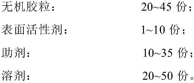
The invention discloses a thermal radiation coating for an automobile lamp. The thermal radiation coating for the automobile lamp is prepared from the following components in parts by weight: 10 to 25 parts of carbon nano-tubes, 20 to 45 parts of inorganic colloidal particles, 1 to 10 parts of a surfactant, 20 to 50 parts of a solvent, and 10 to 35 parts of other auxiliary agents. The thermal radiation coating disclosed by the invention mainly has the characteristics that heat on the surface of a decorative ring and in the decorative ring are radiated out of a lamp cavity at the infrared wavelength of 1 to 15 [mu]m by utilizing the high heat conductivity of the carbon nano-tubes, high infrared emission rate of the inorganic colloidal particles and the adhesion capacity of the organic surfactant, so that the surface temperature of a brushed or sprayed component is reduced, and mist in a lamp cavity is reduced. The thermal radiation coating obtained in the invention has the characteristics of high heat resistance temperature, high chemical stability, low volatility, convenience in coating, damp and heat resistance, temperature cycling resistance and the like, and can be applied to coating components, such as the decorative ring of the automobile lamp and the radiator, of an automobile.

Description

technical field [0001] The invention relates to a radiation heat dissipation coating, in particular to a heat dissipation coating for car lamps, and belongs to the technical field of polymer coatings. Background technique [0002] With the continuous development of automobile lamp technology, the main engine manufacturers are paying more and more attention to the fogging problem of the light distribution mirror of the lamp. The reasons for the fogging of car lights can be attributed to three categories: first, the air flow in the lamp cavity is not smooth, and the temperature difference between the inside and outside of the lamp cavity at the local dead corner is large, and the air condenses to produce fog after encountering the light distribution mirror; The local temperature in the state is too high, and the hot air encounters the light distribution mirror to condense to form fog; the third is that the small molecule volatiles in the lamp cavity are adsorbed on the surface...

Claims


Application Information

Patent Timeline
Patent Type & Authority Applications(China)
IPC IPC(8): C09D1/00C09D7/12
CPCC09D1/00C09D5/18
Inventor 尹群杰陈兆禹李志兵
Owner HASCO VISION TECHNOLOGY CO LTD
Learn More