Biasing circuit, clock circuit, chip and electronic equipment

A technology of bias circuit and clock circuit, applied in electrical components, power oscillator, etc., can solve the problem of low precision of clock signal

Pending Publication Date: 2017-10-13
GREE ELECTRIC APPLIANCES INC
View PDF0 Cites 7 Cited by
  • Summary
  • Abstract
  • Description
  • Claims
  • Application Information

AI Technical Summary

Problems solved by technology

[0004] In the process of realizing the present invention, the inventor found that the traditional clock circuit has at least the following problems: Since each discrete component of the bias circuit is easily affected by the temperature of the surrounding environment of the chip, the precision of the clock signal output by the RC clock circuit is not high

Method used


Image

  • Biasing circuit, clock circuit, chip and electronic equipment
  • Biasing circuit, clock circuit, chip and electronic equipment
  • Biasing circuit, clock circuit, chip and electronic equipment

Examples


Embodiment Construction

[0026] In order to make the object, technical solution and advantages of the present invention clearer, the present invention will be further described in detail below in conjunction with the accompanying drawings and embodiments. It should be understood that the specific embodiments described here are only used to explain the present invention, not to limit the present invention.

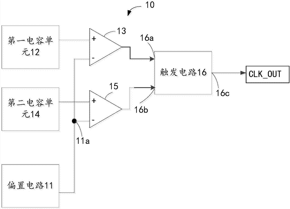
[0027] An embodiment of the present invention provides a clock circuit. The clock circuit is used in various integrated chips, and it can output a clock signal with a certain clock period. For example, the clock signal is a square wave with a duty cycle of 50% high level and a duty cycle of 50% low level. Signal. Therefore, a clock signal consists of levels corresponding to two 1 / 2 clock periods. Under the control of the clock signal, the chip works in an orderly manner according to the programmed logic. The chip can be a general-purpose processor, digital signal processor (DSP), application-spe...


PUM


Abstract

The invention relates to the technical field of integrated circuits, in particular to a biasing circuit, a clock circuit, a chip and electronic equipment. The biasing circuit includes an operational circuit used for inputting reference voltage, a first electric current source used for supplying first electric current, a switch circuit, and a compensating circuit which is linked to a first node and used for providing second electric current, wherein the magnitude of third electric current flowing through a zero-temperature coefficient circuit is equal to the sum of the magnitude of the first electric current and the magnitude of the second electric current. Since the reference voltage remains unchanged and the total resistance of the zero-temperature coefficient circuit is out of the influence of temperature and remains unchanged, the third electric current flowing through the zero-temperature coefficient circuit remains the same. Compared with a traditional technique, obviously, the deviation value of calculation can be decreased. Moreover, the compensating circuit can supply the second electric current, obviously, and by the compensation effect of the compensating circuit, the voltage fluctuation of an external power source or the influence caused on the calculation of the first electric current by the resistance interference of the switch can be reduced.

Description

technical field [0001] The invention relates to the technical field of integrated circuits, in particular to a bias circuit, a clock circuit, a chip and electronic equipment. Background technique [0002] The clock circuit is an important module in the microprocessor chip, and its performance is of great significance to the microprocessor chip. [0003] The traditional clock circuit adopts the RC clock circuit, and the RC clock circuit is widely used in integrated circuits because of its classic structure. Wherein, the bias circuit is widely used in the RC clock circuit, and the bias circuit outputs a clock signal in cooperation with the RC clock circuit by outputting a bias voltage. [0004] In the process of implementing the present invention, the inventor found at least the following problems in the traditional clock circuit: Since each discrete component of the bias circuit is easily affected by the temperature of the surrounding environment of the chip, the precision o...

Claims


Application Information

Patent Timeline
Patent Type & Authority Applications(China)
IPC IPC(8): H03B5/04
CPCH03B5/04
Inventor 徐以军彭新朝张亮冯玉明白效宁殷惠萍谢育桦范世荣王静
Owner GREE ELECTRIC APPLIANCES INC
Why Eureka
Try Eureka