Electrostatic thawing refrigerator

An electrostatic and refrigerator technology, applied in the field of defrosting refrigerators, can solve problems such as poor airflow circulation, discounted cooling and heating effects, and achieve the effects of avoiding temperature regulation, reducing thawing time difference, and overcoming large wind resistance area.

Pending Publication Date: 2017-10-13
老娘舅餐饮股份有限公司
View PDF7 Cites 3 Cited by
  • Summary
  • Abstract
  • Description
  • Claims
  • Application Information

AI Technical Summary

Problems solved by technology

The disadvantage is that the circulation of the airflow in the cabinet is up-and-down circulation. Due to the large area of ​​the shelf in the up-down direction, the airflow circulation is blocked, resulting in poor airflow circulation and greatly reduced cooling and heating effects.

Method used


Image

  • Electrostatic thawing refrigerator
  • Electrostatic thawing refrigerator
  • Electrostatic thawing refrigerator

Examples


Embodiment 1

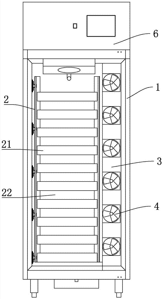
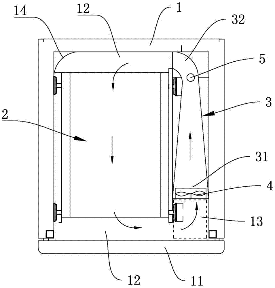
[0020] Embodiment 1: as figure 1 and figure 2 As shown, an electrostatic thawing refrigerator includes a box body 1, a thawing shelf 2 arranged in the box body 1, an electrostatic induction device capable of generating a high-voltage electrostatic field, and a temperature control device 6 for cooling or heating the box body 1 . The front side of the box body 1 is provided with a box door 11, the left side of the thawing shelf 2 is fixed on the inner wall of the left side of the box body 1 through an insulating seat, and the right side of the thawing shelf 2 is fixed on the left and right sides of the box body 1 through an insulating seat on the fixed bracket. The thawing rack 2 includes several thawing trays 21 stacked up and down, and the quantity is determined by the actual situation. The two vertically adjacent thawing trays 21 are arranged at intervals and a spacer 22 is formed between the vertically adjacent two thawing trays 21 , and the static induction device is co...

Embodiment 2

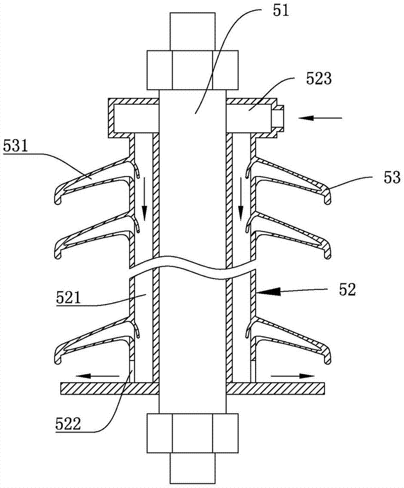
[0024] Embodiment 2: as image 3 and Figure 4 As shown, the difference from Embodiment 1 is that a heat dissipation sleeve 52 is provided on the outside of the heating rod 51, and the wall of the heat dissipation sleeve 52 is a hollow structure, and a flow channel 521 is provided inside, and an air inlet is provided at the upper end of the heat dissipation sleeve 52. The terminal 523 and the air intake terminal 523 blow air to the flow channel 521 through the blower, and the lower end of the cooling sleeve 52 is provided with a lower opening. The outer side of the heat dissipation sleeve 52 is provided with heat dissipation fins 53 spaced up and down, and the heat dissipation fins 53 are inclined downward from the root to the end. A cavity 531 is provided in the heat dissipation fin 53 , and a first opening 532 is provided at the joint between the lower surface of the heat dissipation fin 53 and the heat dissipation sleeve 52 , and the first opening 532 communicates with the...


PUM


Abstract

The invention relates to the technical field of thawing refrigerators, in particular to an electrostatic thawing refrigerator. The electrostatic thawing refrigerator comprises a refrigerator body, a thawing shelf, an electrostatic induction device and a temperature control device. The thawing shelf comprises a plurality of thawing plates which are stacked up and down. Every two adjacent upper and lower thawing plates are arranged in a spaced mode, and the position between every two adjacent upper and lower thawing plates forms a spacing region. Air guide regions are formed between the front and rear sides of the thawing shelf and the front and rear sides of the refrigerator body. The spacing regions communicate with the air guide regions on the front side and the rear side. A flow guide groove is formed in the refrigerator body and communicates with the air guide regions on the front side and the rear side, a heating assembly is disposed at one end of the flow guide groove, and a blowing assembly is disposed at the other end of the flow guide groove. By means of the electrostatic thawing refrigerator, the problems that the air resistance area of the thawing shelf in the air flowing direction is large, circulation flow of air flow in the refrigerator body is not smooth, and temperature difference occurs due to non-uniform heat dissipation are solved, the thawing time difference of upper frozen food and lower frozen food is reduced, and the situation that the temperature control device is repeatedly started for temperature controlling due to inconsistent temperature of the upper portion and lower portion is avoided.

Description

technical field [0001] The invention relates to the technical field of thawing refrigerators, in particular to an electrostatic thawing refrigerator. Background technique [0002] At present, there are many kinds of equipment and products for food preservation and thawing in the market. Among them, the products using electrostatic technology adopt the method of adding electrostatic induction devices to ordinary refrigerators or freezers to realize the thawing of frozen items and the thawing of food. Keep fresh. However, there has always been a problem that has plagued people. When such products and equipment are thawed, the temperature in the cabinet is inconsistent, and the temperature difference between the upper part and the bottom will reach 1 to 3 degrees Celsius. For example: the application number is 2006201206619 Chinese utility model patent described a kind of rapid thawing fresh-keeping cabinet, comprising: the diversion groove installed on the inner wall of one s...

Claims


Application Information

Patent Timeline
Patent Type & Authority Applications(China)
IPC IPC(8): F25D11/00F25D23/12F25D17/06
CPCF25D11/00F25D17/062F25D23/12
Inventor 杨国民
Owner 老娘舅餐饮股份有限公司
Why Eureka
Try Eureka