
Novel regulating valve

A regulating valve, a new type of technology, applied in the field of regulating valves, can solve the problems of high internal pressure, easy damage to the regulating valve body, and inability to dredge water or air, so as to prolong the service life, avoid long-term impact damage, and enhance the anti-scouring performance Effect

Active Publication Date: 2017-10-10
YANGZHONG FIRST BUTTERFLY VALVE FACTORY
View PDF7 Cites 2 Cited by
  • Summary
  • Abstract
  • Description
  • Claims
  • Application Information

AI Technical Summary

Problems solved by technology

[0002] The structure of the regulating valve in the prior art is simple, it only has the function of regulating, and it cannot dredge the internal water or air well when it is closed, resulting in excessive internal pressure, which is easy to damage the regulating valve body

Method used


Image

  • Novel regulating valve
  • Novel regulating valve

Examples


Embodiment Construction

[0015] The present invention will be further described below in conjunction with the accompanying drawings. The following examples are only used to illustrate the technical solution of the present invention more clearly, but not to limit the protection scope of the present invention.

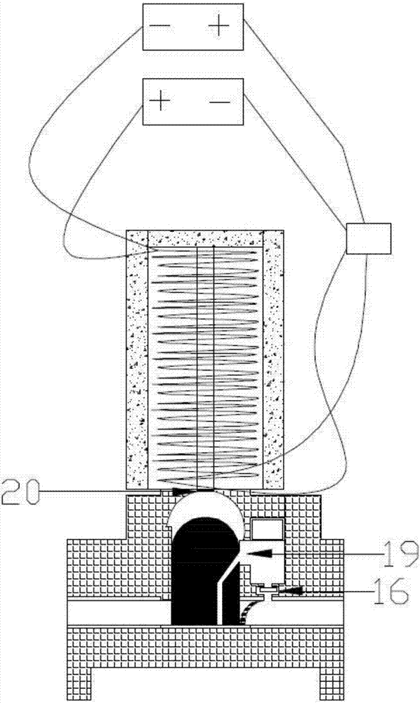
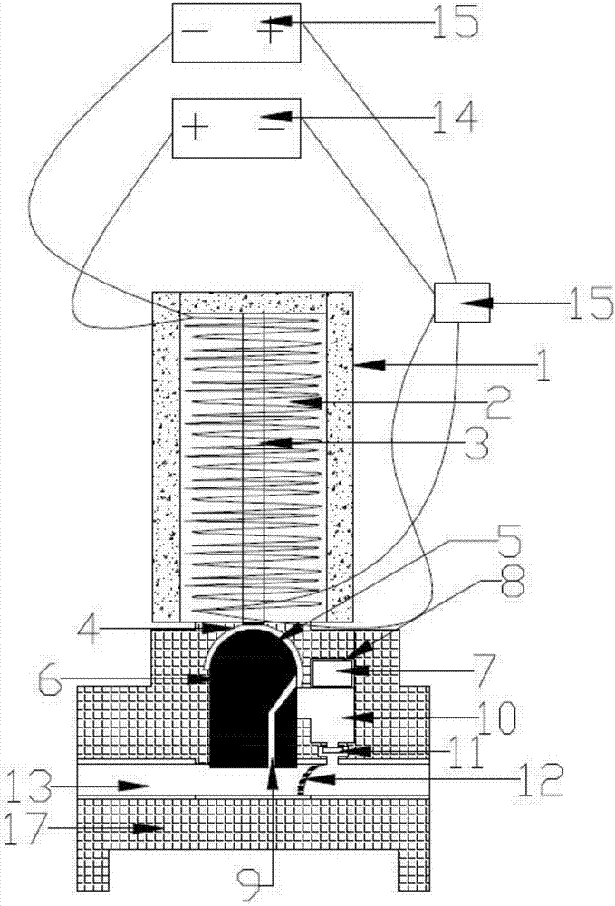
[0016] A new type of regulating valve, including a magnetically insulating frame 1, an electromagnetic coil 2, a ferromagnetic core 3, a piston 5, a flood discharge chamber 10, a one-way door mechanism allowing water to flow out of the flood discharge chamber 10 in one direction, a pipe 13, and a forward power supply 14. Switch 15, reverse power supply 18 and housing 17; the magnetically insulated frame 1 is fixed above the housing 17, and the upper end of the ferromagnetic core 3 is fixed in the inner top of the magnetically insulated frame 1 On the wall, the electromagnetic coil 2 is wound on the ferromagnetic core 3, a central slot 6 is opened in the center of the housing 17, and a through ho...


PUM


Abstract

The invention discloses a novel regulating valve. A magnetism-insulating frame body is fixedly arranged above a shell. An iron magnetic core is fixedly arranged in the magnetism-insulating frame body. An electromagnetic coil is wound on the iron magnetic core. A center groove is formed in the shell. A through hole is formed in the top of the center groove, the center groove communicates with the magnetism-insulating frame body through the through hole, and a plastic plate is fixedly arranged at the through hole in a sealing mode. A piston is slidably connected into the center groove and is a magnet. A pipeline is arranged in the shell and penetrates through the lower portion of the center groove. A flood discharging chamber is formed in the shell, a flood discharging hole is formed in the center groove, and the center groove communicates with the flood discharging chamber through the flood discharging hold. A through hole is formed in the bottom wall of the piston, and the piston communicates with the flood discharging hole through the through hole. A one-way door mechanism is fixedly arranged in the flood discharging chamber. Switches include the two forward switches and the two reversed switches. The forward switches, the two ends of the electromagnetic coil, and a forward power supply are connected in series. The reversed switches, the two ends of the electromagnetic coil and a reversed power supply are connected in series. When the novel regulating valve stops operating, the piston is tightly attached to the pipeline under the effect of magnetic force so as to close the pipeline, residual water enters the flood discharging chamber through a communication hole and enters a water outlet of the pipeline through a stepped through hole, and thus scour resistance of the novel regulating valve is improved.

Description

technical field [0001] The invention relates to a novel regulating valve, which belongs to the technical field of regulating valves. Background technique [0002] The regulating valve in the prior art has a simple structure and only has a regulating function, and cannot well dredge the water or air inside when it is closed, resulting in excessive internal pressure, which is easy to damage the regulating valve body. Contents of the invention [0003] The technical problem to be solved by the present invention is to overcome the defects of the prior art and provide a new erosion-resistant regulating valve. [0004] In order to achieve the above purpose, the present invention provides a new type of regulating valve, which includes a magnetically insulating frame, an electromagnetic coil, a ferromagnetic core, a piston, a flood discharge chamber, a one-way door mechanism that allows water to flow out of the flood discharge chamber in one direction, a pipeline, a positive Powe...

Claims


Application Information

Patent Timeline
Patent Type & Authority Applications(China)
IPC IPC(8): F16K3/26F16K31/06F16K39/04F16K47/08
CPCF16K3/26F16K31/0668F16K39/04F16K47/08
Inventor 许瑞华
Owner YANGZHONG FIRST BUTTERFLY VALVE FACTORY
Learn More